Solid electrolytic capacitor assembly
a technology of electrolytic capacitors and components, applied in the direction of variable capacitors, fixed capacitors, fixed capacitor details, etc., can solve problems such as capacitor damag
- Summary
- Abstract
- Description
- Claims
- Application Information
AI Technical Summary
Benefits of technology
Problems solved by technology
Method used
Image
Examples
example 1
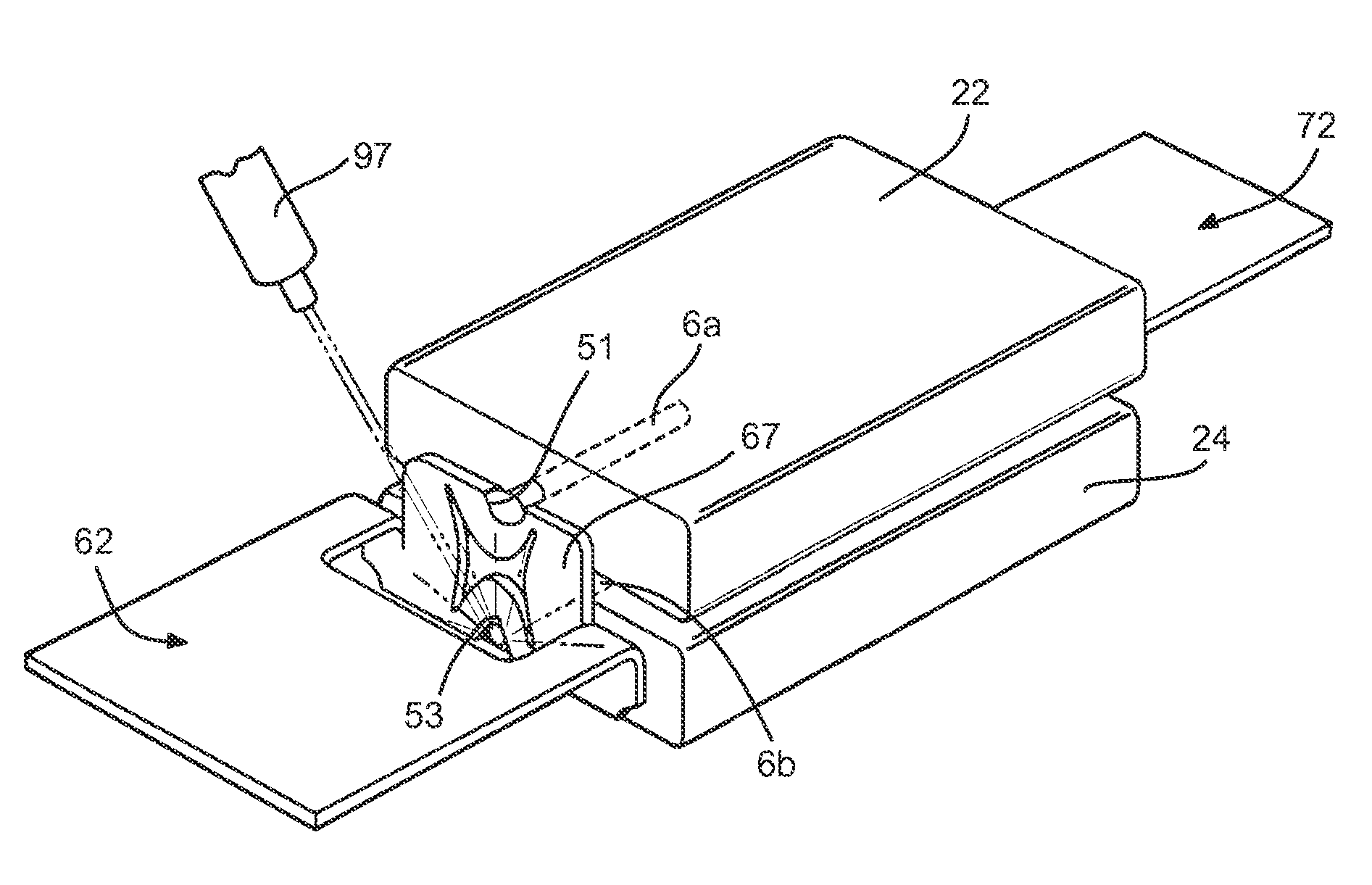
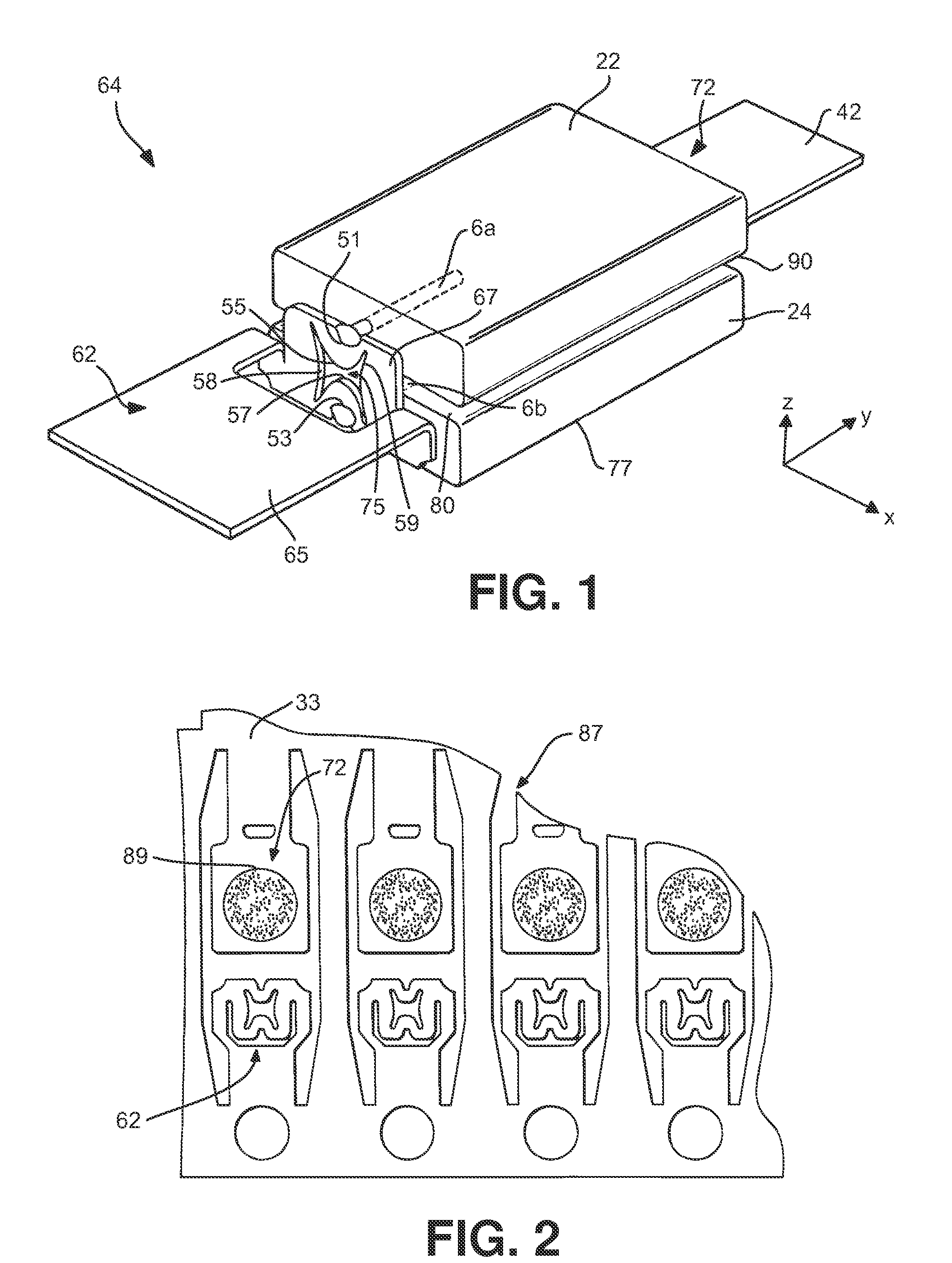
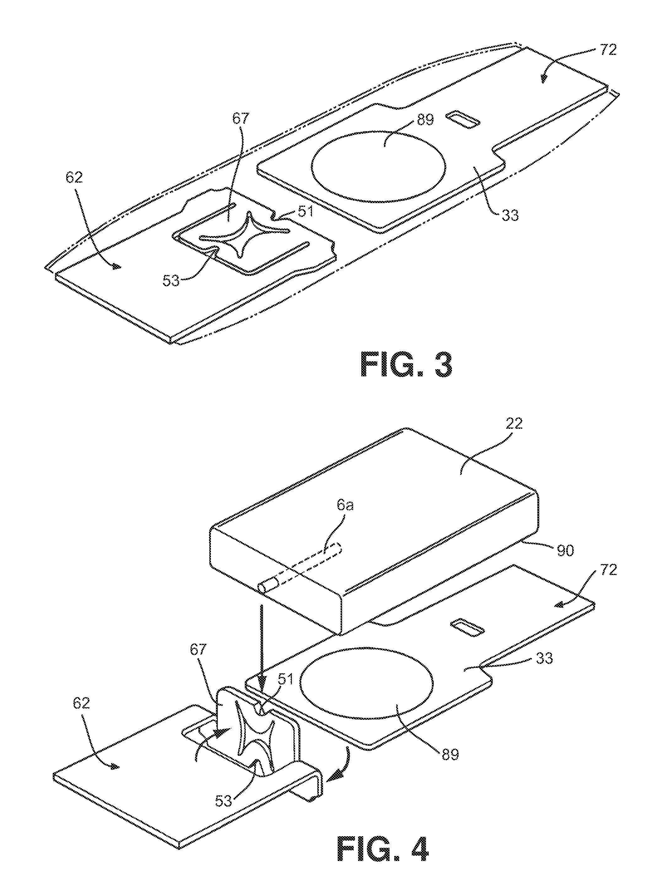
[0052]Capacitor assemblies were constructed from two tantalum capacitor elements as described above and shown in FIGS. 1-8. The tantalum powder used to form each capacitor element had a specific charge of 150,000 μF*V / g (available from H.C. Starck). The tantalum powder was pressed using known techniques so that the resulting pellets had a length of about 5.35 millimeters, a width of 3.7 millimeters, and a thickness of 0.75 millimeters. The pellets were sintered at 1245° C. for 10 minutes. The pellets were anodized at a voltage of 15 volts, impregnated with manganese dioxide, and then coated with graphite and silver layers in the manner described above. Each individual tantalum part had a capacitance of about 500 μF. The parts were then connected in parallel to common anode and cathode terminations as described above so that the final capacitance of the assembly was about 1000 μF and the rated voltage was 4 Volts. The capacitor assemblies were encapsulated in a case having a length o...
example 2
[0056]Capacitor assemblies were constructed from two niobium oxide (“NbO”) capacitor elements as described above and shown in FIGS. 1-8. The niobium oxide powder used to form the capacitor elements had a specific charge of 80,000 μF*V / g (available from H.C. Starck). The niobium oxide powder was pressed using known techniques so that the resulting pellets had a length of about 5.35 millimeters, a width of 3.7 millimeters, and a thickness of 0.75 millimeters. The pellets were sintered at 1380° C. for 10 minutes. The pellets were anodized at a voltage of 27 volts, impregnated with manganese dioxide, and then coated with graphite and silver layers in the manner described above. Each individual niobium oxide part had a capacitance of about 110 μF. The parts were then connected in parallel to common anode and cathode terminations as described above so that the final capacitance of the assembly was about 220 μF and the rated voltage was 4 Volts. The capacitor assemblies were encapsulated i...
example 3
[0057]Capacitor assemblies were constructed as described in Example 2, except that the anode was fluted and a forming voltage of 21 volts was employed. The fluted anode had two parallel grooves extending on each side along the entire anode length (-x direction). Each groove had a width of 0.4 millimeters and a thickness of 0.25 millimeters. The fluted anode has a length of 5.35 millimeters, a width of 3.7 millimeters, and a thickness of 0.76 millimeters.
PUM
 Abstract
Description
Claims
Application Information
 - R&D
- Intellectual Property
- Life Sciences
- Materials
- Tech Scout
- Unparalleled Data Quality
- Higher Quality Content
- 60% Fewer Hallucinations
Browse by: Latest US Patents, China's latest patents, Technical Efficacy Thesaurus, Application Domain, Technology Topic, Popular Technical Reports.
© 2025 PatSnap. All rights reserved.Legal|Privacy policy|Modern Slavery Act Transparency Statement|Sitemap|About US| Contact US: help@patsnap.com


