
Controlling data packet flows by manipulating data packets according to an actual manipulation rate

a data packet and data processing technology, applied in data switching networks, instruments, frequency-division multiplexes, etc., can solve problems such as data packet loss, data packet overflow, packet loss of several packets, etc., to achieve optimal router utilization, reduce queuing delays, and high accuracy

Inactive Publication Date: 2008-12-23
IBM CORP
View PDF4 Cites 17 Cited by
  • Summary
  • Abstract
  • Description
  • Claims
  • Application Information

AI Technical Summary

Benefits of technology

The patent describes a method for controlling data packet flows in a network device by manipulating data packets based on their actual manipulation rate. This rate is determined by analyzing traffic conditions over the entire network and can be used to avoid congestion at the network device. The method can involve dropping or marking data packets, and can impact data packet flows either directly or indirectly by soft means such as dropping or marking data packets. The method is efficient and effective in optimizing packet flow and utilizing network resources without the need for manual adjustment.

Problems solved by technology

Once no acknowledgment is received within the timer period, the data packet is regarded as lost.
Whenever a packet loss occurs, the sender assumes that the packet was dropped by intermediate routers due to link congestion.
Link congestion typically results from exceeding the transmit rate on the link as well as the given limited buffer space in the router.
Within one RTT several packet losses might occur.
However, TCP adapts too slowly on links with a long round-trip time (RTT) and high bandwidth: TCP increases by roughly 10 kbit / RTT; for RTT=200 ms—e.g. on a transatlantic link—, a single TCP connection requires 100 RTT=20 s to re-claim a 1 Mbit / s link, or 10 s to recover after a drop-to-half rate reduction which occurs whenever a loss event occurs.
For a RTT=50 ms —which is a typical RTT for a link within a country or a continent—, 100 000 RTT would be required to adapt, which is roughly 1.5 h and thus not very useful.
Together with the constant pressure from TCP to expand its bandwidth, this assures that temporary congestion and thus packet loss will happen.
Efficiently dealing with packet loss is hard, as TCP will react harshly to packet loss, as discussed above.

Method used


Image

  • Controlling data packet flows by manipulating data packets according to an actual manipulation rate
  • Controlling data packet flows by manipulating data packets according to an actual manipulation rate
  • Controlling data packet flows by manipulating data packets according to an actual manipulation rate

Examples


Embodiment Construction

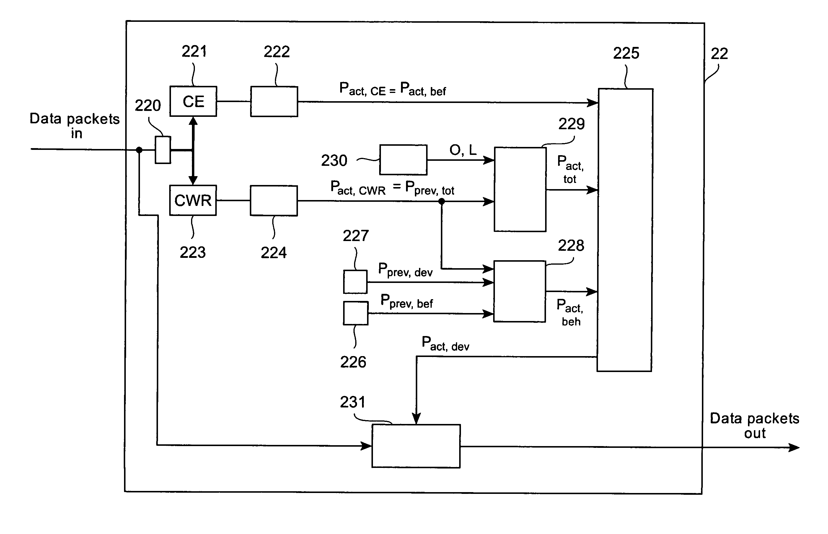
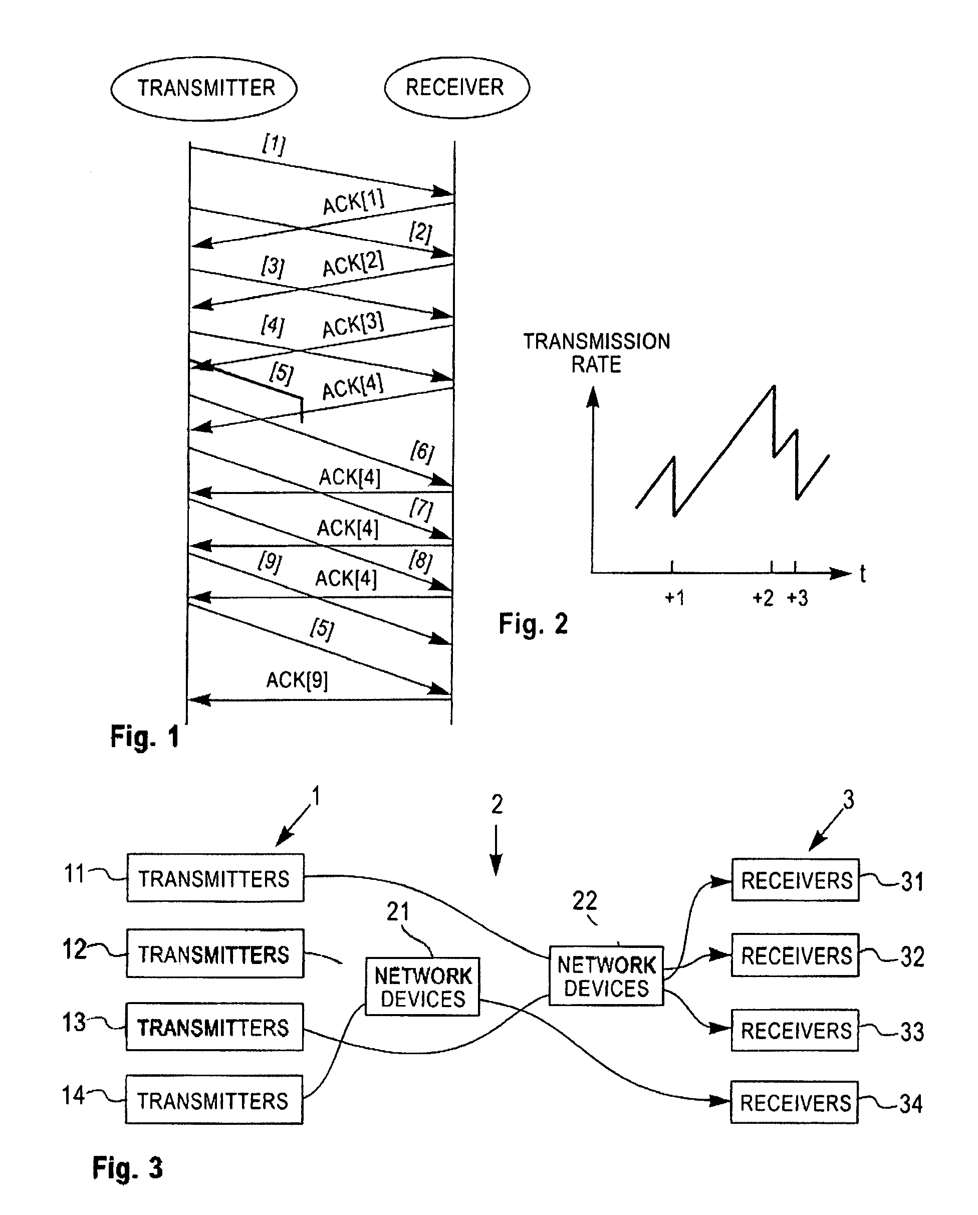
[0053]FIG. 3 illustrates a block diagram of a network with transmitters 1, in particular transmitters 11, 12, 13, 14, with receivers 3, in particular receivers 31, 32, 33, 34, and network devices 2, in particular network devices 21 and 22. Arrows represent data flows from respective transmitters 1 to respective receivers 3 via network devices 2. The diagram shows of only a simplified structure of a network. Network device 22 for example is supposed to support the proposed methods for controlling data flows. Not necessarily all network devices within a network have to support one of the proposed methods, since an overall benefit with regard to congestion control can be achieved even when only selected network devices, or even only one network device implements a method proposed.

[0054]In all further embodiments illustrated in the following figures, it is made use of a congestion notification scheme that is known as Explicit Congestion Notification (ECN [RFC3168]). The corresponding RF...


PUM


Abstract

A method for controlling data packet flows in a network device by manipulating data packets according to an actual manipulation rate. Amongst data packets received by a network device such as a router, data packets are identified that are marked with a pattern according to a congestion notification scheme. A pattern rate of data packets comprising such a pattern is determined, and the actual manipulation rate is determined subject to the pattern rate.

Description

TECHNICAL FIELD[0001]The present invention relates to methods for controlling data packet flows in a network device by manipulating data packets according to an actual manipulation rate.DESCRIPTION OF PRIOR ART[0002]The dominant transport protocol used today in the Internet is TCP, the Transmission Control Protocol, which is encapsulated in the Internet Protocol (IP). TCP is used whenever reliable transmission is needed, such as for the World Wide Web, wherein the Hypertext Transport Protocol, HTTP, and the File Transfer Protocol, FTP, utilize TCP.[0003]Reliable data transport in TCP is based on the acknowledgment of transmitted data packets. A TCP data packet transmitted from a sender to a receiver is expected to be acknowledged by the receiver upon receipt. There are several ways to find out whether a data packet got lost on its way from sender to receiver. For instance, the sender sets a timer when a data packet is sent. Once no acknowledgment is received within the timer period,...

Claims


Application Information

Patent Timeline
Patent Type & Authority Patents(United States)
IPC IPC(8): H04L12/26H04L12/56
CPCH04L47/10H04L47/12H04L47/193H04L47/283
Inventor MANNAL, SOENKEPLETKA, ROMAN A.WALDVOGEL, MARCEL
Owner IBM CORP
Learn More