Hierarchical bus structure and memory access protocol for multiprocessor systems

a multiprocessor system and bus structure technology, applied in the direction of memory systems, electrical apparatus construction details, instruments, etc., can solve the problems of large number of signal lines, unsatisfactory delays, and significant chip area, and achieve the effect of improving bus utilization

Inactive Publication Date: 2008-12-23
NVIDIA CORP
View PDF43 Cites 10 Cited by
  • Summary
  • Abstract
  • Description
  • Claims
  • Application Information

AI Technical Summary

Benefits of technology

[0015]In accordance with another aspect of the invention, the address and data portions of each shared-memory access operation are performed as separate bus transactions that are separated in time. For example, a given processor may perform a first bus transaction to transfer a memory address and associated command to a particular bus cycle assignment unit during its assigned slot. On a subsequent assigned slot (e.g., during the next round robin cycle or after multiple round robin cycles), this processor may perform a second bus transaction to send or receive the data associated with that memory address and command. Between these two bus transactions, some or all of the other processors that can access the same shared memory may perform their own respective transactions. Thus, bus transactions associated with multiple pending memory access operations are interleaved on a bus in a manner that significantly improves bus utilization. In one embodiment, all bus transactions are performed during a single, fixed-length slot that has an effective duration of one clock cycle (pipelined).

Problems solved by technology

Master devices are in charge of significant state change decisions in the system and may make arbitrary and unsolicited bus requests, while targets typically respond when something is specifically requested of them.
However, burst accesses can cause undesirable delays when several CPU's share a memory, particularly if one CPU hogs the memory.
This improves the utilization of the bus but adds considerable complexity because (a) the target ordinarily must become a master for returning data, and must know where to return this data, and c) the arbiter services more devices.
However, this approach can lead to a large number of signal lines and significant chip area when dozens of processors are to be replicated on the chip.

Method used


Image

  • Hierarchical bus structure and memory access protocol for multiprocessor systems
  • Hierarchical bus structure and memory access protocol for multiprocessor systems
  • Hierarchical bus structure and memory access protocol for multiprocessor systems

Examples


Embodiment Construction

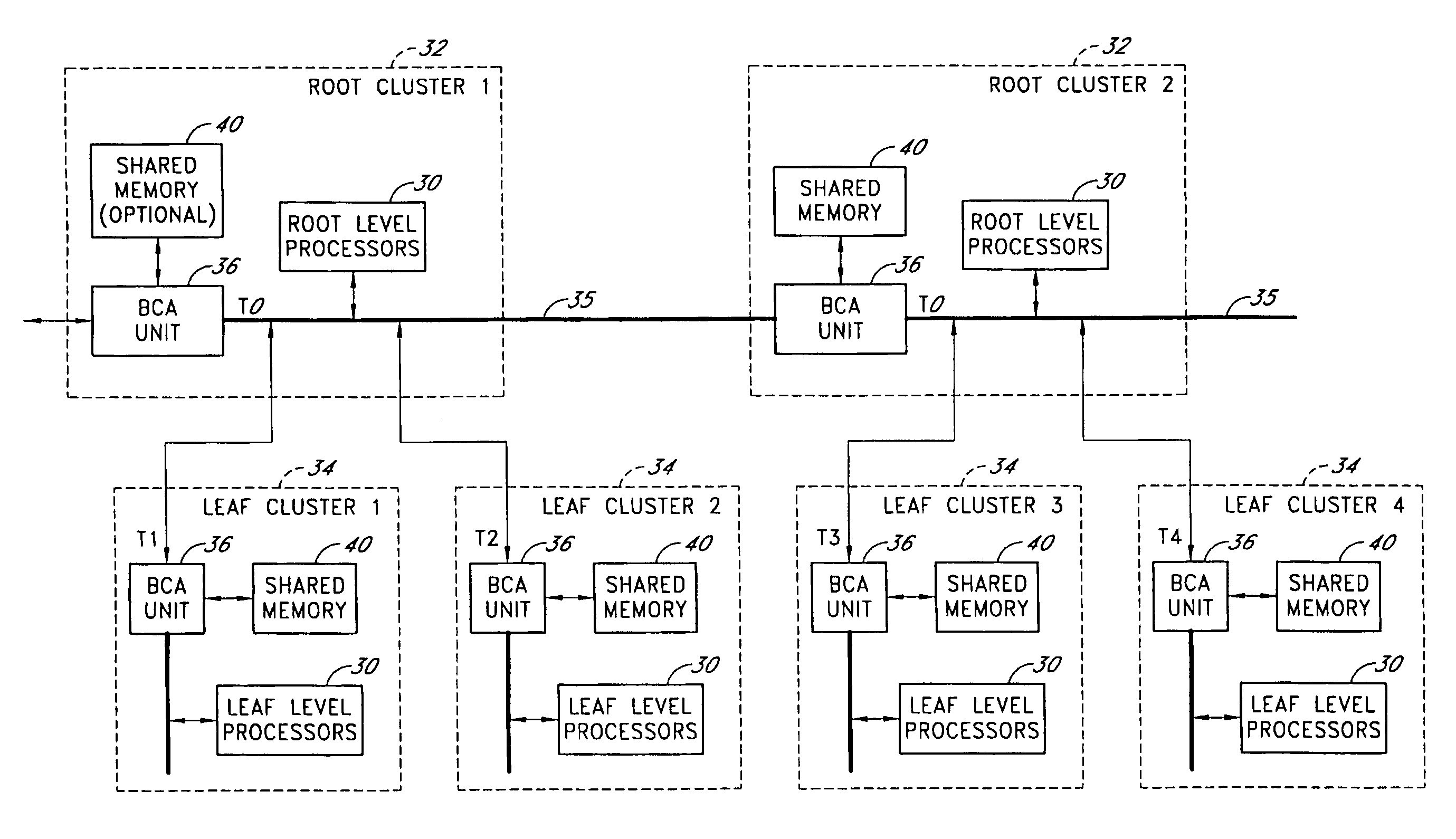
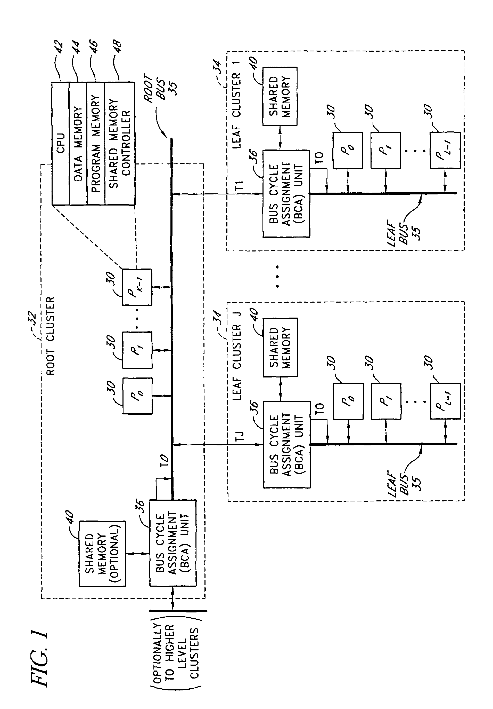
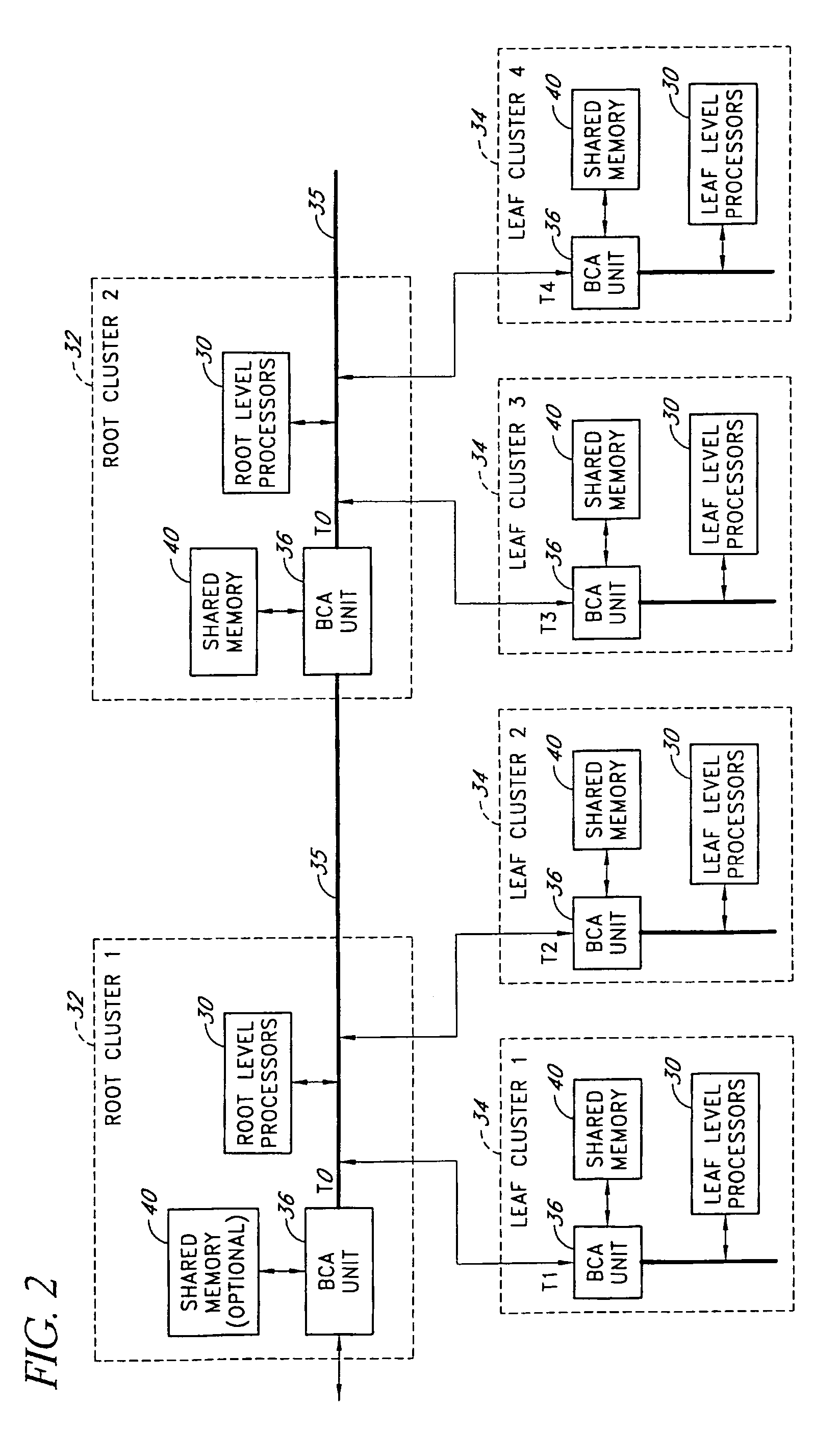
[0022]The present invention provides a hierarchical bus structure through which clusters of processors may be arranged and interconnected within a hierarchy to facilitate processor communications via shared memories. The bus structure is well suited for voice processing applications in which clusters of embedded processors processes voice streams in parallel, although the architecture is not so limited.

[0023]The invention also provides an improved memory access protocol and bus interface for controlling processor accesses to a shared memory. This access protocol and bus interface are preferably incorporated into the hierarchical bus structure, but also have independent utility.

I. Overview of Hierarchical Bus Structure

[0024]FIG. 1 illustrates a hierarchical processor arrangement in which processors 30 are arranged within a single root cluster 32 and J leaf clusters 34. (A cluster is referred to herein as a “leaf” cluster if it does not have any sibling clusters, and is referred to as...


PUM

PropertyMeasurementUnit
bandwidthaaaaaaaaaa
chargeaaaaaaaaaa
timeaaaaaaaaaa

Abstract

A hierarchical bus structure is disclosed in which clusters of processors are arranged and interconnected within a hierarchy to facilitate processor communications via shared memories. The bus structure is well suited for voice processing applications in which clusters of embedded processors process voice streams in parallel, although the architecture is not so limited. Also disclosed is a memory access protocol in which the address and data portions of shared-memory access operations are performed as separate bus transactions that are separated in time, such that multiple concurrent memory access operations from different processors may be interleaved over a shared bus.

Description

CROSS-REFERENCE TO RELATED APPLICATIONS[0001]The present application is a continuation of U.S. patent application Ser. No. 10 / 369,340 filed Feb. 18, 2003 now U.S. Pat. No. 7,085,866, which claims the benefit under 35 U.S.C. §119(e) of U.S. Provisional Application No. 60 / 358,133 filed Feb. 19, 2002 and U.S. Provisional Application No. 60 / 358,290 filed Feb. 19, 2002. Said U.S. patent application Ser. No. 10 / 369,340, said U.S. Provisional Application No. 60 / 358,133, and said U.S. Provisional Application No. 60 / 358,290 are hereby incorporated by reference herein in their entireties.FIELD OF THE INVENTION[0002]The present invention relates generally to computer and bus architectures for computing systems that use clusters of processors.BACKGROUND OF THE INVENTION[0003]Computer buses are typically used to connect a central processing unit (CPU) with other significant resources, such as memory or I / O devices. The CPU typically acts as a master and the other devices typically serve as targe...

Claims


Application Information

Patent Timeline
Patent Type & Authority Patents(United States)
IPC IPC(8): G06F13/00C06C5/06G06F13/368G06F15/167
CPCG06F13/1657
Inventor HOBSON, RICHARD F.RESSL, BILLDYCK, ALLAN R.
Owner NVIDIA CORP
Why Eureka
Try Eureka