Underwater cutting pelletizer

a pelletizer and water chamber technology, applied in the field of underwater cutting pelletizers, can solve the problems of affecting the cutting work of resin, deteriorating and occurrence of variations in the retention time of the cut pellets in the water chamber, so as to achieve the effect of reducing the temperature of the pellets and ensuring the quality of the pellets

Inactive Publication Date: 2008-12-30
KOBE STEEL LTD
View PDF16 Cites 26 Cited by
  • Summary
  • Abstract
  • Description
  • Claims
  • Application Information

AI Technical Summary

Benefits of technology

[0013]The present invention has been accomplished in view of the above-mentioned problems and it is an object of the invention to provide an underwater cutting pelletizer having a water chamber which permits pellets introduced therein to be discharged promptly to the exterior of the water chamber and which can attain a uniform retention time of the pellets therein.
[0022]According to the present invention the retention time of cut pellets in the interior of the water chamber can be made substantially uniform and variations in temperature of the pellets can be kept to a minimum. Besides, the retention time of the pellets can be made as short as possible and the contact of the pellets with the inner wall of the water chamber and the cutter can be prevented.

Problems solved by technology

However, if the flow of the cooling water is not smooth and the cooling water stagnated within the water chamber, the cut pellets may stay for a long time within the water chamber or conversely may be discharged in a too short time from the water chamber.
Thus, there is a possibility that the pellets cooling time may not coincide with a predetermined cooling time, with consequent deterioration in quality of the pellets.
When the pellets stay for a long time within the water chamber, it is likely that the remaining pellets may strike against the cutter or the inner wall of the water chamber, or may stock each other, exerting a bad influence on the resin cutting work.
The flow of cooling water is apt to stagnate in the vicinity of joined portions between the inlet portions and the water chamber and a joined portion between the outlet portion and the water chamber and pellets staying in the stagnation are not discharged to the exterior of the water chamber, further, complicated flows are formed within the water chamber by the flows of cooling water from the plural inlet portions and agitation of the cooling water caused by rotation of the cutter in the water chamber, resulting in occurrence of variations in the intra-water chamber retention time of cut pellets.
These phenomena give rise to a difference in pellets cooling time, with a great possibility of occurrence of variations in the quality, shape and size of pellets.
Moreover, since plural inlet portions are provided, a layout design and fabrication of cooling water supply pipes become complicated and as the case may be the flow of cooling water within the water chamber depends on the positional relation of plural inlet portions and outlet portion and the flow rate of cooling water.

Method used


Image

  • Underwater cutting pelletizer
  • Underwater cutting pelletizer
  • Underwater cutting pelletizer

Examples


Embodiment Construction

[0040]An underwater cutting pelletizer according to the present invention will be described hereinunder with reference to the accompanying drawings.

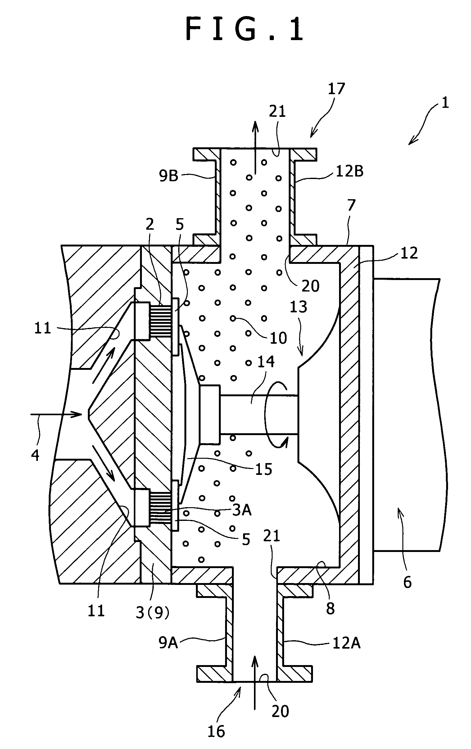
[0041]FIG. 1 is a sectional side view of the underwater cutting pelletizer indicated at 1.

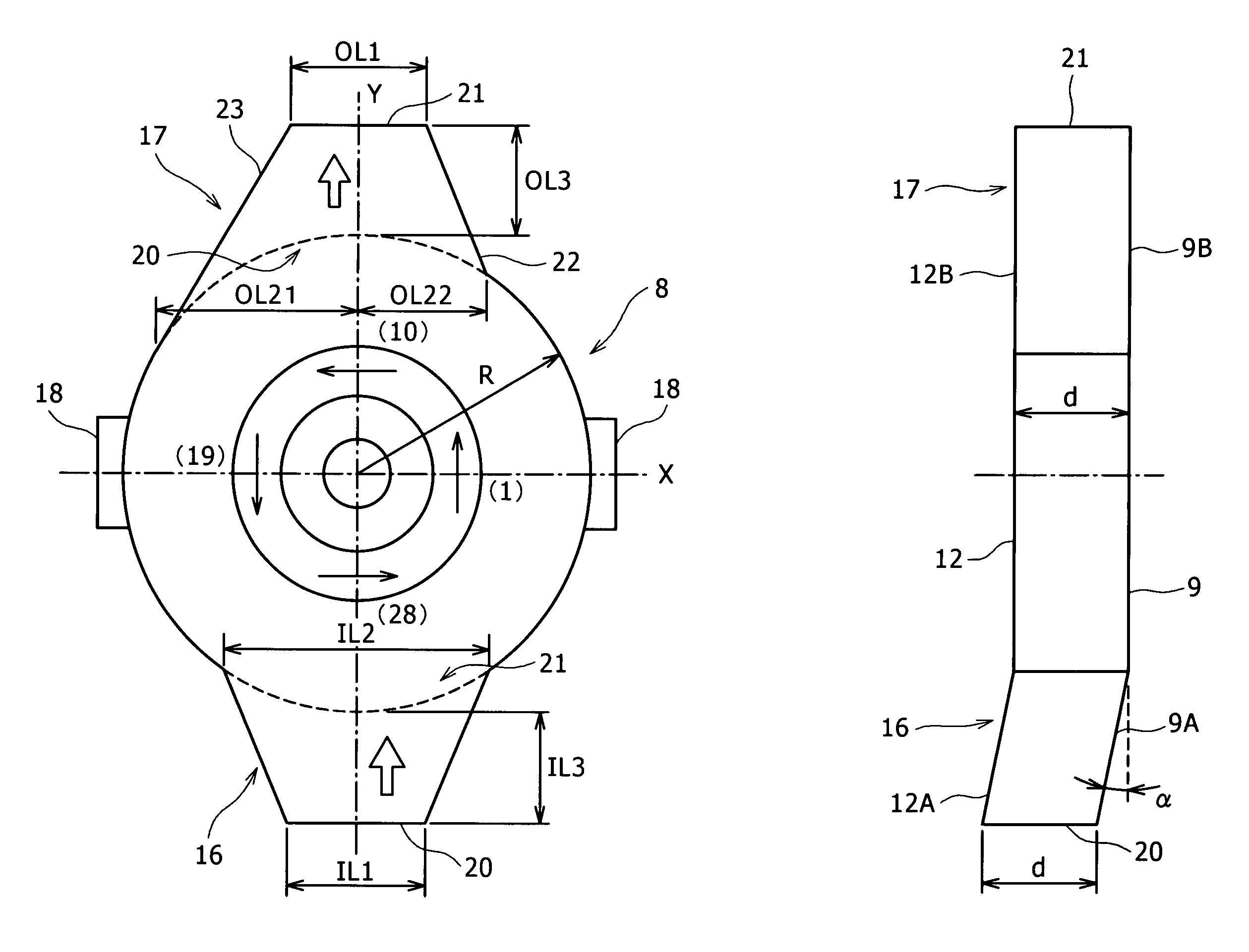
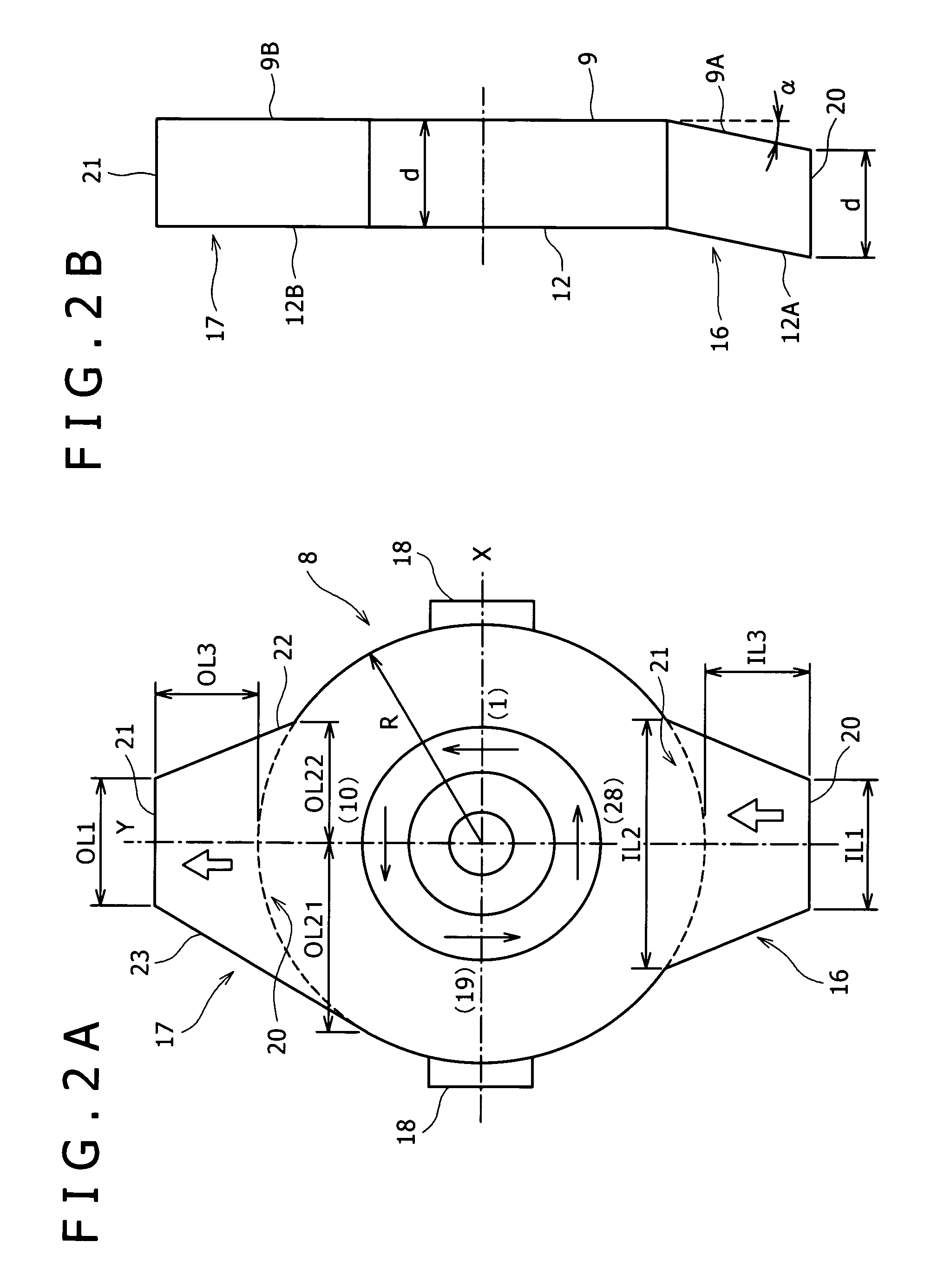
[0042]The underwater cutting pelletizer 1 includes a die plate 3 having a large number of nozzles 2 (die holes) and a cutter 5 adapted to move along a cutting surface 3A on the die plate 3 to cut off molten resin 4 (molten material to be processed) which is extruded from the nozzles 2. The underwater cutting pelletizer 1 further includes drive means 6 for rotating the cutter 5 on the die plate 3.

[0043]The die plate 3 and the cutter 5 are installed in the interior of a circulation box 7. The interior of the circulation box 7 forms a water chamber 8 which surrounds the die plate 3 and the cutter 5. Alower wall 9 (the left side wall in FIG. 1) of the water chamber 8 is constituted by the die plate 3. A twin-screw extruder or a gear pump or the like is ...


PUM

PropertyMeasurementUnit
angleaaaaaaaaaa
inclination αaaaaaaaaaa
Reynolds numberaaaaaaaaaa

Abstract

An underwater cutting pelletizer is disclosed wherein a water chamber is circular in plan, an inlet portion is formed on one side in a diametrical direction of the water chamber to introduce cooling water into the water chamber, and an outlet portion is formed on the other side in the diametrical direction of the water chamber to discharge the cooling water from the interior of the water chamber to the exterior, the inlet portion being in a divergent shape in an inflow direction of cooling water. The retention time of pellets in the interior of the water chamber can be made as short as possible.

Description

BACKGROUND OF THE INVENTION[0001]1. Field of the Invention[0002]The present invention relates to an underwater cutting pelletizer for use in producing resin pellets.[0003]2. Description of the Related Art[0004]As known well, an underwater cutting pelletizer for use in producing resin pellets is disposed on a downstream side of an extruder and is provided with a die plate, the die plate having nozzles through which molten resin (molten material to be processed) is extruded, and a cutter for cutting the resin extruded from the nozzles into pellets while rotating. In addition, there is provided a circulation box which covers the die plate and the cutter. The interior of the circulation box serves as a water chamber filled with circulating cooling water.[0005]The water chamber is provided with an inlet portion for introducing cooling water into the interior of the water chamber. Cooling water supplied into the water chamber through the inlet portion not only cools the die plate and the ...

Claims


Application Information

Patent Timeline
Patent Type & Authority Patents(United States)
IPC IPC(8): B29B9/10
CPCB29B9/065Y10T83/9319Y10T83/9464B29C48/0022B29C48/05B29C48/345B29C48/885B29C48/911
Inventor FUKUTANI, KAZUHISAHONKE, KOICHIIRITANI, KAZUONAGAMI, NOBUKI
Owner KOBE STEEL LTD
Why Eureka
Try Eureka