
Aspiration and flushing needle

Inactive Publication Date: 2008-12-30
COOK MEDICAL TECH LLC +1
View PDF8 Cites 26 Cited by
  • Summary
  • Abstract
  • Description
  • Claims
  • Application Information

AI Technical Summary

Benefits of technology

[0013]It will be noted that in all these embodiments of the invention the aspiration cannula is within the flushing needle. This provides an annular lumen for the flushing media but more importantly it provides an aspiration cannula free of any internal obstructions which enables minimum damage to the oocyte during its travel through the aspiration cannula. The two lumen design provides the ability to aspirate and flush simultaneously. It is preferable to aspirate at a slightly greater flow rate than the rate of supply of flushing liquid to gradually deflate the follicle.
[0018]There may be provided a tapered extension on the gripper surrounding the aspiration cannula which extends into connector portion in use. There can be provided an O-ring seal on the tapered extension to improve sealing of the aspiration cannula assembly into the handle.
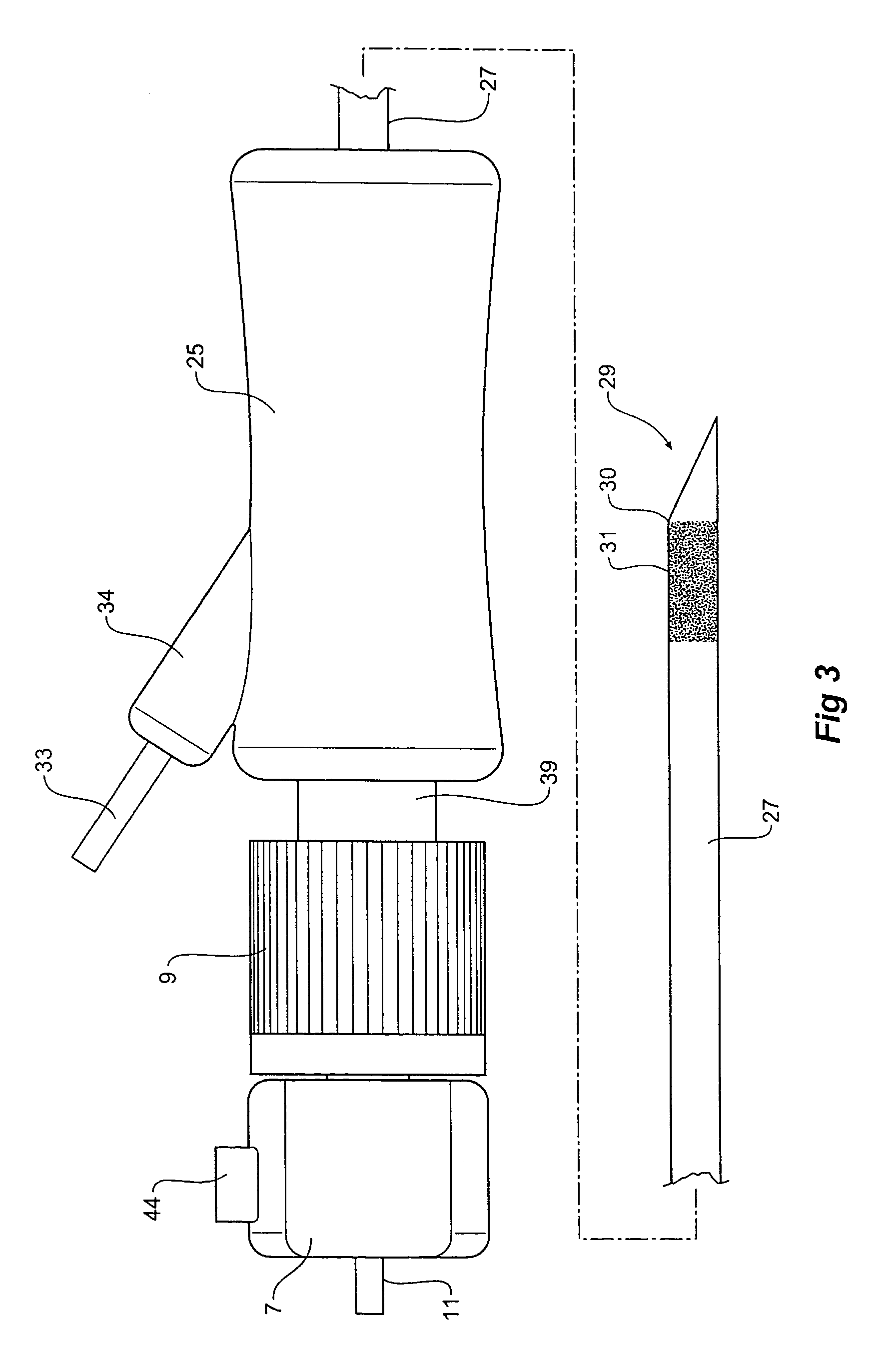
[0023]Preferably the side port on the handle is aligned with the base of the bevel at the distal tip of the outer needle to facilitate tactile alignment of the tip of the needle whereby a physician can determine the position of the tip of the bevel within a patient with respect to a portion of the assembly outside the patient. The side port also provides the physician with a good gripping portion on the handle to assist with rotation of the aspiration and needle assembly as required.
[0034]It is advantageous to supply the aspiration assembly according to the present invention in a disassembled state so that a surgeon or physician can be satisfied that all components are clean and ready to use before assembling them for use. Each component can easily be flushed with flushing medium to ensure that there is no air trapped in them before assembly.
[0036]The flushing lumen or fluid path between the aspiration cannula and the flushing cannula has a dual purpose, not only is it used to convey the flushing medium but it may also be used to control and maintain oocyte temperature during retrieval and in so doing minimizing the damage that may be caused to the oocyte due to rapid temperature changes and exposure to temperatures lower than 37 degrees Celsius. The flushing medium may be heated to a temperature equal to or above the ideal transfer temperature for an oocyte (37° X).
[0037]Once vacuum has been applied to the aspiration lumen, fluid is simultaneously passed through the flushing lumen by means of a mechanical syringe pump or similar. The rate at which fluid is passed through the flushing lumen is preferably lower than the aspiration rate so allowing for a positive flow rate to be achieved within the follicle to assist with removal of the oocyte.

Problems solved by technology

Therefore, the use of a single-lumen device may create the potential of losing the oocyte during the irrigation procedure.
The use of separate paths thereby reduces the possibility of flushing an oocyte out of the aspiration path during an irrigation procedure.

Method used


Image

  • Aspiration and flushing needle
  • Aspiration and flushing needle
  • Aspiration and flushing needle

Examples


Embodiment Construction

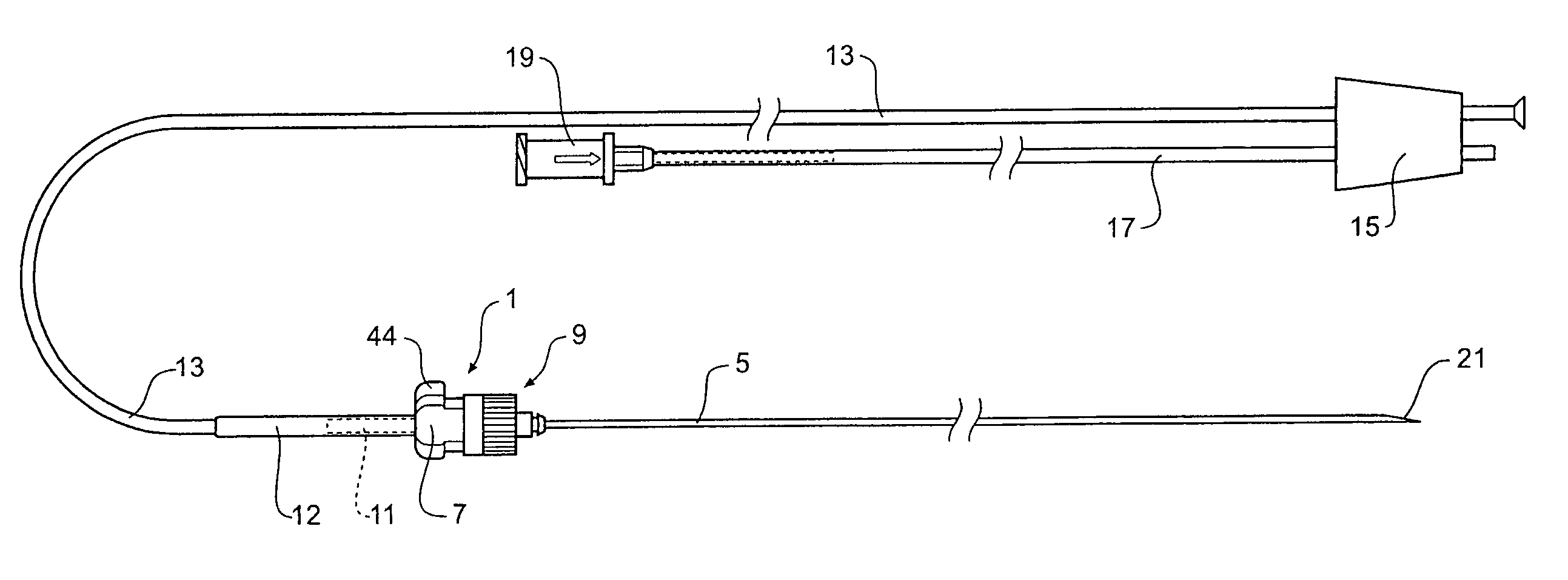
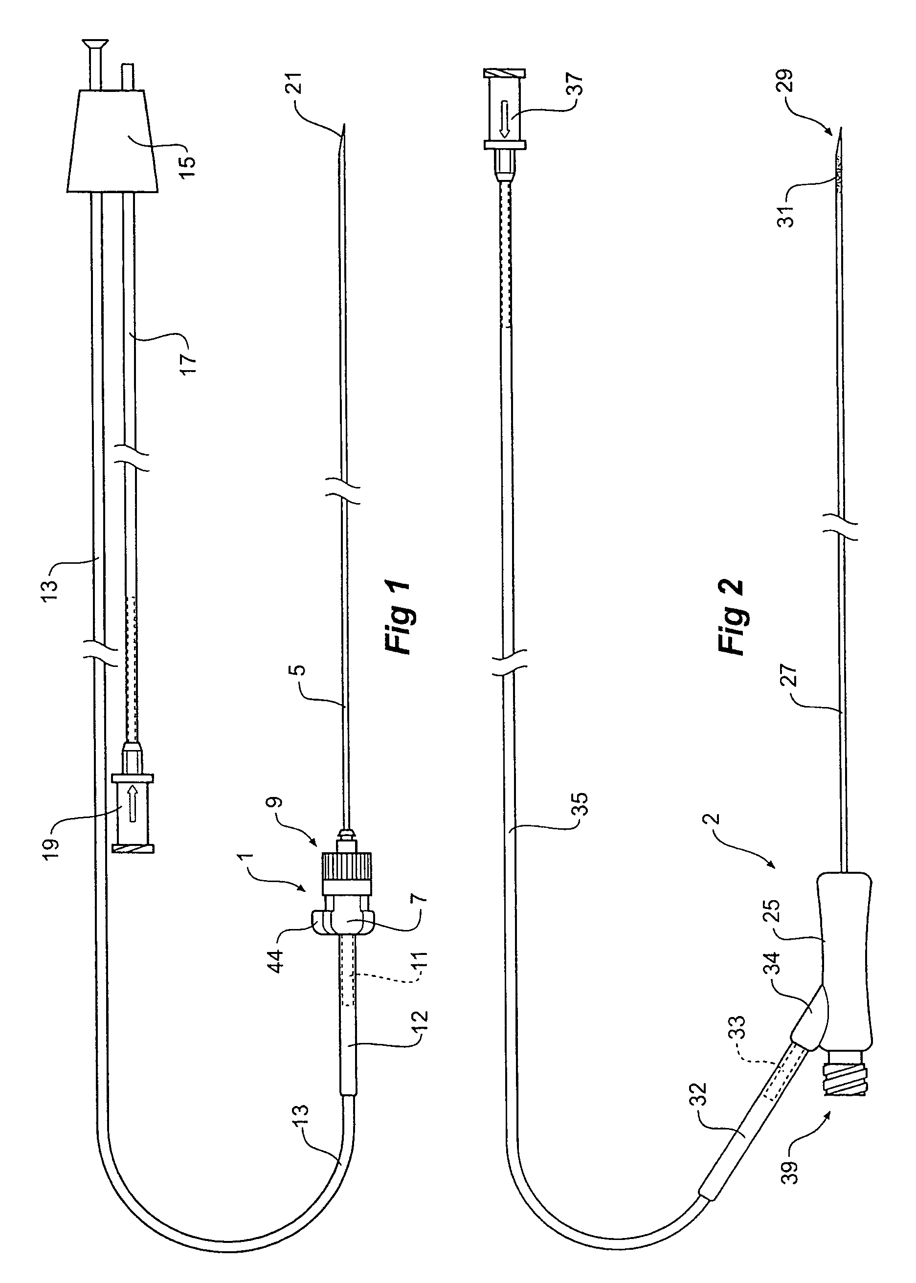
[0047]Now looking more closely at the drawings it will be noted that the aspiration and flushing needle assembly of one embodiment of the present invention comprises an aspiration cannula assembly generally shown as 1 in FIG. 1 and an outer needle assembly generally shown as 2 in FIG. 2.

[0048]The aspiration cannula assembly 1 shown in FIG. 1 includes an aspiration cannula 5 extending from a gripper portion 7. A male Luer lock arrangement 9 extends from the gripper portion 7 and is adapted to connect to the flushing needle assembly as will be discussed below. The aspiration cannula 5 extends distally from the gripper portion 7 and also the aspiration cannula 5 extends through the gripper and a portion 11 extends proximally of the gripper portion 7. On to this portion 11 a flexible aspiration line 13 extends to a stopper 15 which can be fitted into a test tube. A heat shrink tubing 12 is fitted over the junction between the portion 11 and the flexible aspiration line 13 to protect the...


PUM


Abstract

An aspiration and flushing needle assembly having separable flushing and aspiration assemblies. The flushing assembly (2) has a flushing needle (27) extending from a handle (25) and a flushing fluid line (35) which can be connected to a source of flushing liquid. The aspiration assembly (1) has an aspiration needle (5) with a connector (9) which connects into the rear of the handle and an aspiration line (13) which can be connected to an aspiration arrangement. The flushing and aspiration needle assemblies are joined for use with the aspiration needle extending coaxially within the flushing needle to the distal end (29) of the flushing needle.

Description

CROSS-REFERENCE TO RELATED APPLICATIONS[0001]This application claims priority of provisional application Ser. No. 60 / 459,311, filed Apr. 1, 2003.TECHNICAL FIELD[0002]This invention relates to a medical device and, in particular, to an aspiration and flushing needle arrangement adapted for the removal of oocytes from a female patient.BACKGROUND OF THE INVENTION[0003]During an oocyte retrieval procedure, a relatively long aspiration cannula may be abdominally inserted into a patient so that the distal end of the cannula is in contact with a patient's ovary. The objective is to puncture an individual follicle on the ovary and withdraw oocytes through the needle. Generally, the proximal end of the cannula is connected to flexible tubing which is, in turn, connected through a test tube to a vacuum source. The vacuum source provides suction via the test tube to the needle to allow aspiration of the oocyte from the follicle. In some medical procedures to retrieve oocytes the physician may ...

Claims


Application Information

Patent Timeline
IPC IPC(8): A61B17/20A61B17/34A61B17/42A61B17/435A61B19/00A61M1/00
CPCA61B17/435A61B17/3478A61B2017/4233A61B2019/5425A61B2217/005A61B2217/007A61B2090/3925
Inventor JUNGER, MICHAEL CARL
Owner COOK MEDICAL TECH LLC
Learn More