High Z material detection system and method

a detection system and material technology, applied in the field of high z material detection system and method, can solve the problems of not being able to penetrate both detectors with less energy, not being able to equip each one with its own photomultiplier, and current nuclear material detection technology limited to x-ray and gamma ray equipment, etc., to achieve the effect of high z material revealing

Inactive Publication Date: 2008-12-30
CELIGHT
View PDF5 Cites 49 Cited by
  • Summary
  • Abstract
  • Description
  • Claims
  • Application Information

AI Technical Summary

Benefits of technology

[0015]The system and method are disclosed for nuclear materials detection by muon flow sensing. The system comprises a series of muon detectors for efficiently measuring muons deflection caused by the presence of high Z materials.
[0018]In the preferred embodiment the system includes a unit for measuring a transit time for each particular muon entering the system. This also allows taking into consideration the trajectory dependence on the muon velocity leading to more accurate determination of the presence of high Z material. In one embodiment the data processing unit eliminates fault detection caused by low energy muons.
[0021]Another object of the present invention is a method for high Z material revealing, comprising continuously measuring an incident angle of each incoming muon by a first detector; estimating an expected statistics of an expected leaving angle at a second detector for each incoming muon; continuously measuring an actual leaving angle for each incoming muon by the second detector; storing a data on the incident, the actual and the expected leaving angles; calculating an actual statistics of the actual leaving angle; finding a difference between the expected and the actual statistics; and determining a presence of high Z material in between the first and the second muon detector when the difference exceeds a predetermined difference value. In the preferred embodiment the method also includes measuring a time of flight for each particle registered by the first muon detector, and eliminating a contribution of particles that have time of flight larger than a predetermined time value.

Problems solved by technology

The small size of each independent scintillator means that many readout channels (typically tens of thousands) are required, and it is not practical to equip each one with its own photomultiplier.
Other particles originating from i.e. terrestrial radiation will also cause stimulation, but those particles have too less energy to penetrate both detectors.
Current technologies for nuclear material detection are limited to X-ray and Gamma ray equipment.

Method used


Image

  • High Z material detection system and method
  • High Z material detection system and method
  • High Z material detection system and method

Examples


Embodiment Construction

[0030]The present invention now will be described more fully hereinafter with reference to the accompanying drawings, in which the preferred embodiments of the invention are shown. This invention may, however, be embodied in many different forms and should not be construed as limited to the embodiments set forth herein; rather, these embodiments are provided so that this disclosure will be thorough and complete, and will fully convey the scope of the invention to those skilled in the art.

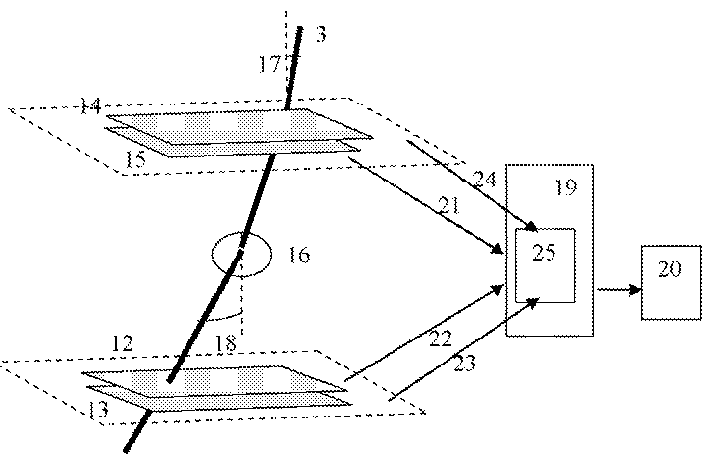
[0031]In one embodiment of the present invention, a system for high Z material detection is proposed as shown in FIG. 3. In the preferred embodiment two detectors 12 and 13 are positioned below the interrogated area, for example, on the ground or under the ground. Similar muon detectors 14 and 15 are positioned above the ground level. Each group of the detectors 12,13 and 14,15 allows measuring the muon incidence angle with an accuracy of at least 1 milliradian and muon coordinate with an accuracy o...


PUM

PropertyMeasurementUnit
time resolutionaaaaaaaaaa
altitudeaaaaaaaaaa
mean energyaaaaaaaaaa

Abstract

A method and system for high Z substance revealing using muon detection technique is presented. Natural muon coordinate and incidence angle are measured above and below the interrogated volume. The data on muons trajectory change caused by the presence of high Z material and the muons time of flight between the upper and lower muon detectors are used for the decision making on the presence of a nuclear substance inside the volume. The system is adapted for performing measurements on moving objects such as moving trucks.

Description

CROSS-REFERENCE TO RELATED APPLICATIONS[0001]The present invention claims is a continuation-in-part of U.S. Ser. No. 11 / 626,920, filed Jan. 25, 2007 and U.S. provisional application Ser. No. 60 / 883,420, filed Jan. 4, 2007, which are fully incorporated herein by reference.FIELD OF INVENTION[0002]This invention relates generally to the systems and methods for revealing hidden uranium, plutonium and other high Z materials using muon detection technique.BACKGROUND OF THE INVENTION[0003]Flow of cosmic rays constantly bombards Earth. Primary cosmic rays consist of single protons (about 90% of all cosmic rays) and alpha particles (majority of the remaining 10%). When these primary cosmic rays hit Earth's atmosphere at around 30,000 m above the surface, the impacts cause nuclear reactions, which produce pions. These pions decay into a muon and muon neutrino at about 9000 m altitude. Many muons decay on the way down into neutrinos and an electron while others reach the surface, and there are...

Claims


Application Information

Patent Timeline
Patent Type & Authority Patents(United States)
IPC IPC(8): G01N23/00G01N23/201
CPCG01T1/2935
Inventor GOLDBERG, JACQUESSHPANTZER, ISAACACHIAM, YAAKOVREINGAND, NADEJDA
Owner CELIGHT
Why Eureka
Try Eureka