Route generating system for an autonomous mobile robot

a technology of autonomous mobile robots and generating systems, which is applied in the direction of process and machine control, distance measurement, instruments, etc., can solve the problems of robots making a clumsy appearance, not easy to design a route for robots, and not the shortest path, so as to reduce computational loads, improve system flexibility, and avoid clumsy appearance in the movement of robots

Active Publication Date: 2009-01-06
HONDA MOTOR CO LTD
View PDF11 Cites 87 Cited by
  • Summary
  • Abstract
  • Description
  • Claims
  • Application Information

AI Technical Summary

Benefits of technology

[0006]A second object of the present invention is to provide a route generating system for an autonomous mobile robot which is easy to program.
[0007]A third object of the present invention is to provide a route generating system for an autonomous mobile robot which allows the robot to avoid an obstacle in a natural way.
[0009]Because the route is generated from a collection of pre-defined edges which are free from obstacles and are selected so as to optimize the generated route, the robot is enabled to travel from the current position to the destination in a safe and optimum fashion. Furthermore, the edges are defined by connecting only those nodes that are relatively close to each other, the candidates of the edges for generating a route can be reduced to a small number and this reduces computational loads. Also, because the route can be selected in a relatively intelligent manner so as to optimize a certain criterion, a clumsy appearance in the movement of the robot can be avoided.
[0010]If the edge defining means is adapted to define additional edges by defining the current position and destination on the map as additional nodes, and the computing means is adapted to compute the route using the additional edges in addition to the regular edges, the current position or the destination is not required to be located in any of the pre-defined nodes, and the flexibility of the system can be enhanced.
[0011]If the nodes include at least one reference mark that can be detected by the robot, the robot is enabled to identify the current position without accumulating errors by adjusting the estimated position of the robot by detecting the reference mark. The input means may be adapted to designate an intermediate point that the robot should pass through as an additional node to increase the freedom of movement of the robot, and such an intermediate point may consist of a reference mark so that the robot may adjust the estimated current position by comparing it with the reference mark as it travels from the current position to the destination.
[0012]To simplify the process of registering the destination and other data, the input means may be provided with a display device showing the area for movement of the robot. As is often the case with an autonomous robot, the current position detecting means may be provided on the robot which is further provided with means for transmitting the detected current position to the input means.

Problems solved by technology

However, a designated area may not have any pre-defined passages as is the case with showrooms and performance stages, and it is not easy to designate a route for the robot when only the destination is given.
This obviously is not the shortest path for the robot to move from the current position to the destination.
Furthermore, the robot would make a clumsy appearance.
However, it would require a highly complex algorithm and increase the computing load.
This would cause a delay in the reaction of the robot and increase the power consumption of the computer.
As a mobile robot typically relies on a battery for its power, a large power consumption is highly undesirable.

Method used


Image

  • Route generating system for an autonomous mobile robot
  • Route generating system for an autonomous mobile robot
  • Route generating system for an autonomous mobile robot

Examples


Embodiment Construction

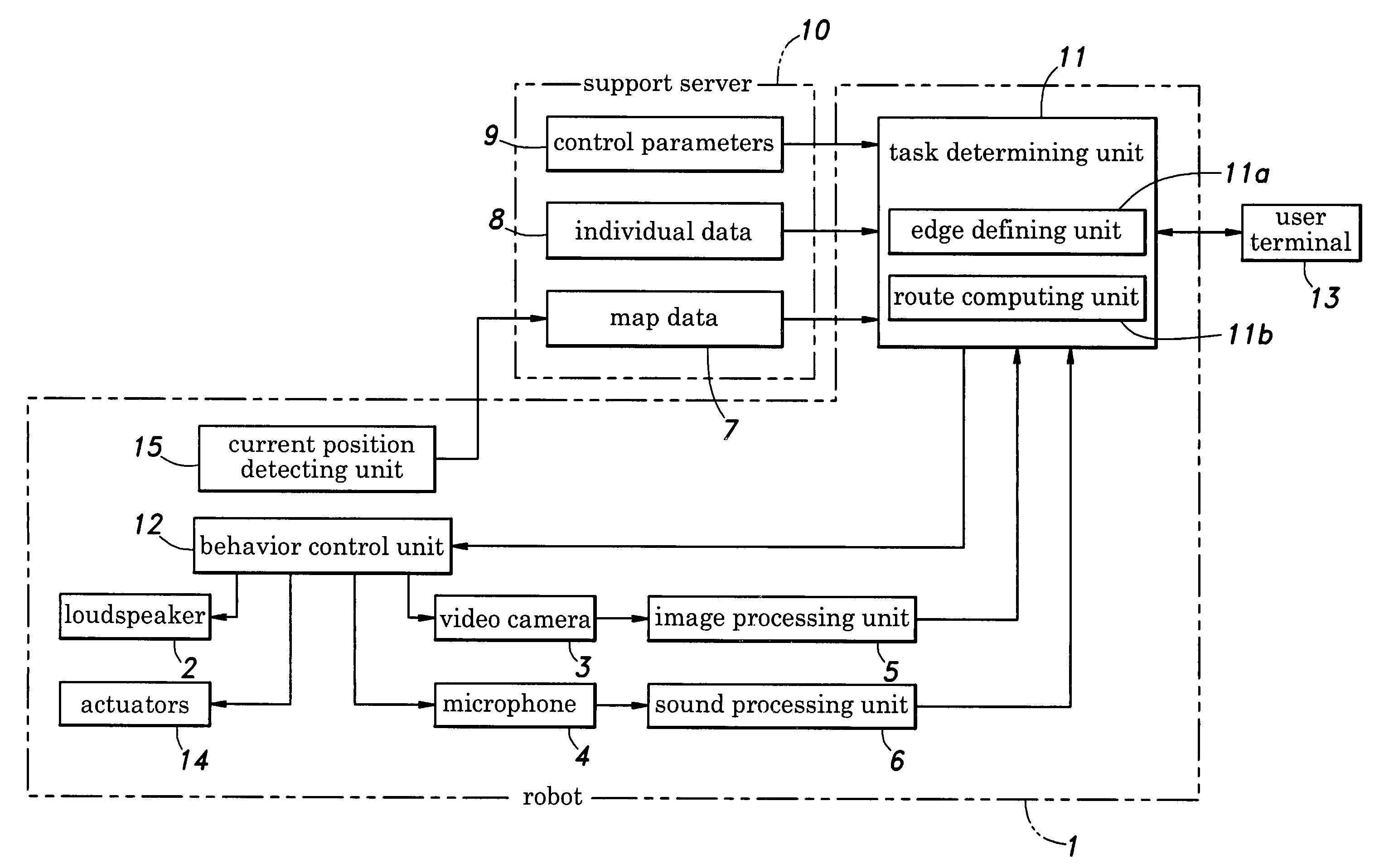
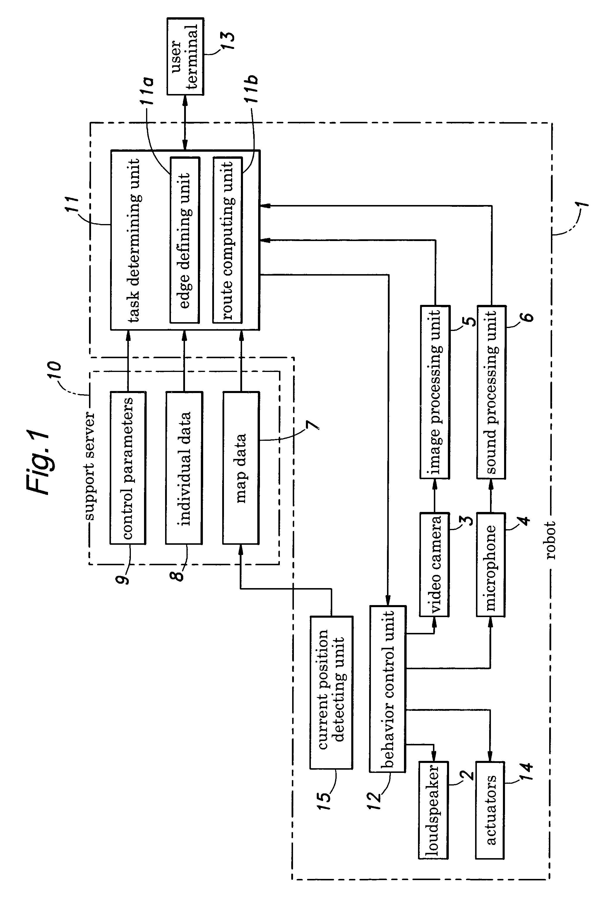
[0021]FIG. 1 is a block diagram showing the overall structure of an autonomous mobile robot embodying the present invention. The robot 1 is provided with a loudspeaker 2, a video camera unit 3 and a microphone unit 4. The image signal obtained from the video camera unit 3 is forwarded to an image processing unit 5, and the audio signal obtained from the microphone unit 4 is forwarded to a sound processing unit 6. A speech signal generated by a speech synthesis unit is forwarded to the loudspeaker 2.

[0022]The video camera unit 3 comprises a pair of monochromatic or color imaging devices, and can be (laterally) panned and (vertically) tilted by means of an electric motor. The image signal from the video camera unit 3 is digitized by a frame grabber, and movement of an object is detected by comparing a pair of adjacent or separated frames. The two imaging devices provide stereographic information on the distance to the object. The image processing unit 5 performs various image processe...


PUM


Abstract

In a route generating system for an autonomous mobile robot, a plurality of nodes are designated within an area of movement of the robot and an edge is defined between a pair of nodes only if a distance from the one node to the other node is less than a threshold value and there is no obstacle on a line drawn between the one point and the other point. Because the route is generated from a collection of pre-defined edges which are free from obstacles and are selected so as to optimize the generated route, the robot is enabled to travel from the current position to the destination in a safe and optimum fashion. Furthermore, the edges are defined by connecting only those nodes that are relatively close to each other, the candidates of the edges for generating a route can be reduced to a small number and this reduces computational loads. Also, because the route can be selected in a relatively intelligent manner so as to optimize a certain criterion, a clumsy appearance in the movement of the robot can be avoided.

Description

TECHNICAL FIELD[0001]The present invention relates to a route generating system for an autonomous mobile robot, and in particular to a route generating system that can simplify programming and reduce computational loads.BACKGROUND OF THE INVENTION[0002]An autonomous mobile robot is required to be capable of moving about in an area where various obstacles are placed from a current position to a destination in a smooth manner while avoiding the obstacles. To provide such a capability to a robot, it has been proposed to prepare an obstacle database containing information on the positions of obstacles in a map of a designated area according to visual information obtained by the robot, and program the route for the robot by looking up the database. See Japanese patent laid open publication No. 2003-266345.[0003]However, a designated area may not have any pre-defined passages as is the case with showrooms and performance stages, and it is not easy to designate a route for the robot when o...

Claims


Application Information

Patent Timeline
Patent Type & Authority Patents(United States)
IPC IPC(8): G05D1/02
CPCG05D1/0214G05D1/0217G05D1/0251G05D1/0274
Inventor MATSUNAGA, SHINICHI
Owner HONDA MOTOR CO LTD
Why Eureka
Try Eureka