Envelope filling machine

a filling machine and envelope technology, applied in document inserters, packaging goods types, transportation and packaging, etc., can solve the problems of reducing the machine operation speed, affecting the quality of the envelope, so as to achieve high reliability and versatility in use, and facilitate the insertion of the envelope. , the effect of simple and functional structur

Active Publication Date: 2009-01-13
CMC SRL
View PDF15 Cites 13 Cited by
  • Summary
  • Abstract
  • Description
  • Claims
  • Application Information

AI Technical Summary

Benefits of technology

[0029]Accordingly, the object of the present invention is to propose an envelope filling machine which introduces sheets into envelopes with a higher operation speed.
[0030]Another object of the present invention is to propose an envelope filling machine, which has a simple and functional structure, and which is highly reliable and versatile in its use.
[0031]Another object of the invention is to propose an envelope filling machine in which swelling of the envelope, due to opening by the air jet, does not shrink the envelope in width as much as to hinder insertion of the sheets.

Problems solved by technology

Obviously, this causes reduction of the machine operation speed and consequently, the production rate is lower than the one which the current high speed sheet and envelope feeding devices would allow.
In case the leading edges of the sheets contact the bottom of the envelope before the envelope is moved clear of the screw shafts, envelope and sheets can get folded and compressed, possibly causing jams.
Conversely, in the leading edges of the sheets contact the bottom of the envelope too late, after that the envelope is moved clear of the screw shafts, insertion of the sheets can be uncompleted.
Such accurate time relation limit the operation speed of the machine.
Also this accurate time relation need limit the operation speed of the machine.

Method used


Image

  • Envelope filling machine
  • Envelope filling machine
  • Envelope filling machine

Examples


Embodiment Construction

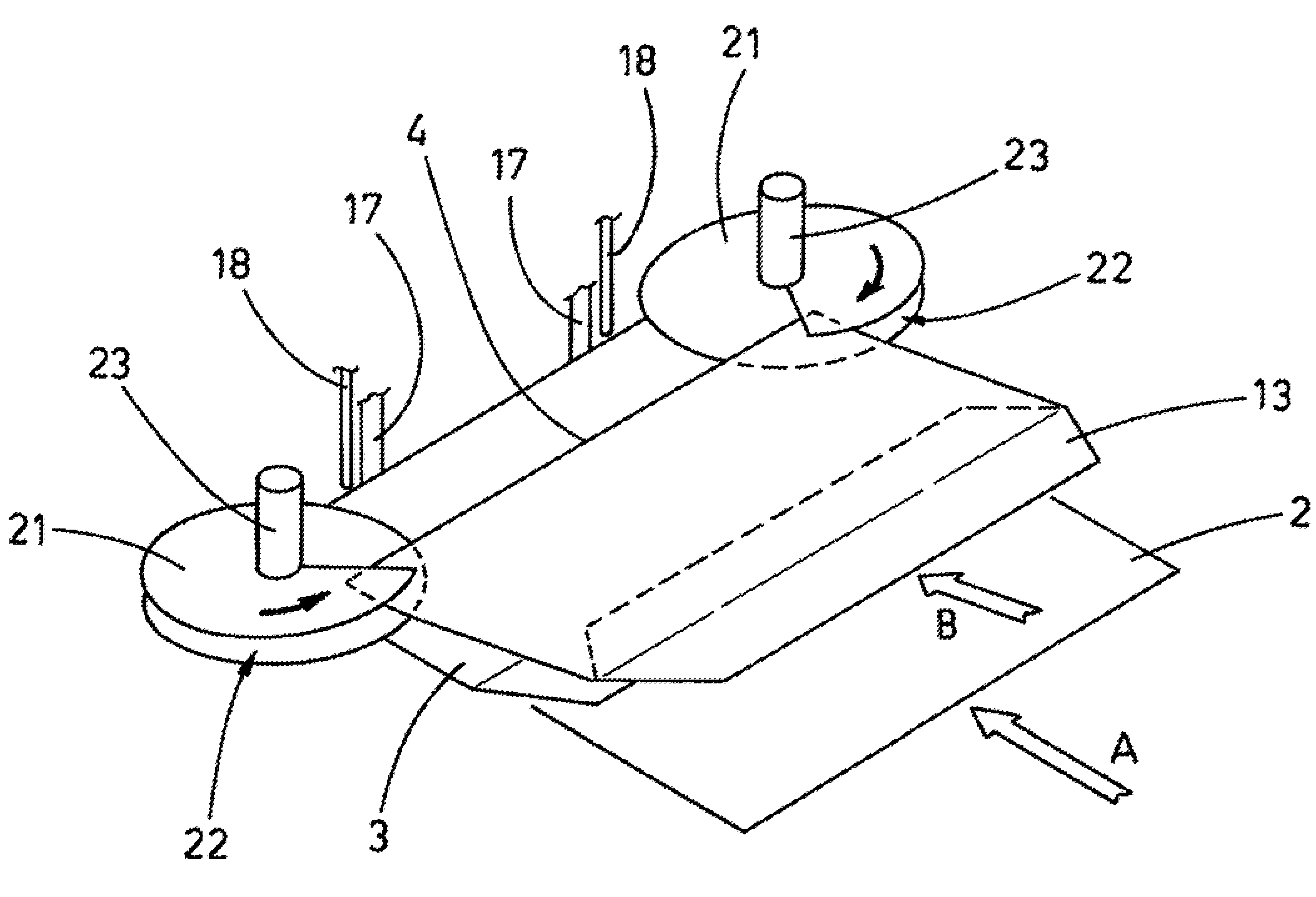
[0037]With reference to the above figures, reference numeral 1 indicates the envelope filling station of the proposed envelope filling machine, which introduces sheets 2 into envelopes 3.

[0038]The sheets 2 are moved along a sliding surface 5. With the word “sheets” not only sheets are in fact meant, but also other items to introduce in the envelopes, such as magazines, booklets, pamphlets, letters, advertisement prints and like items.

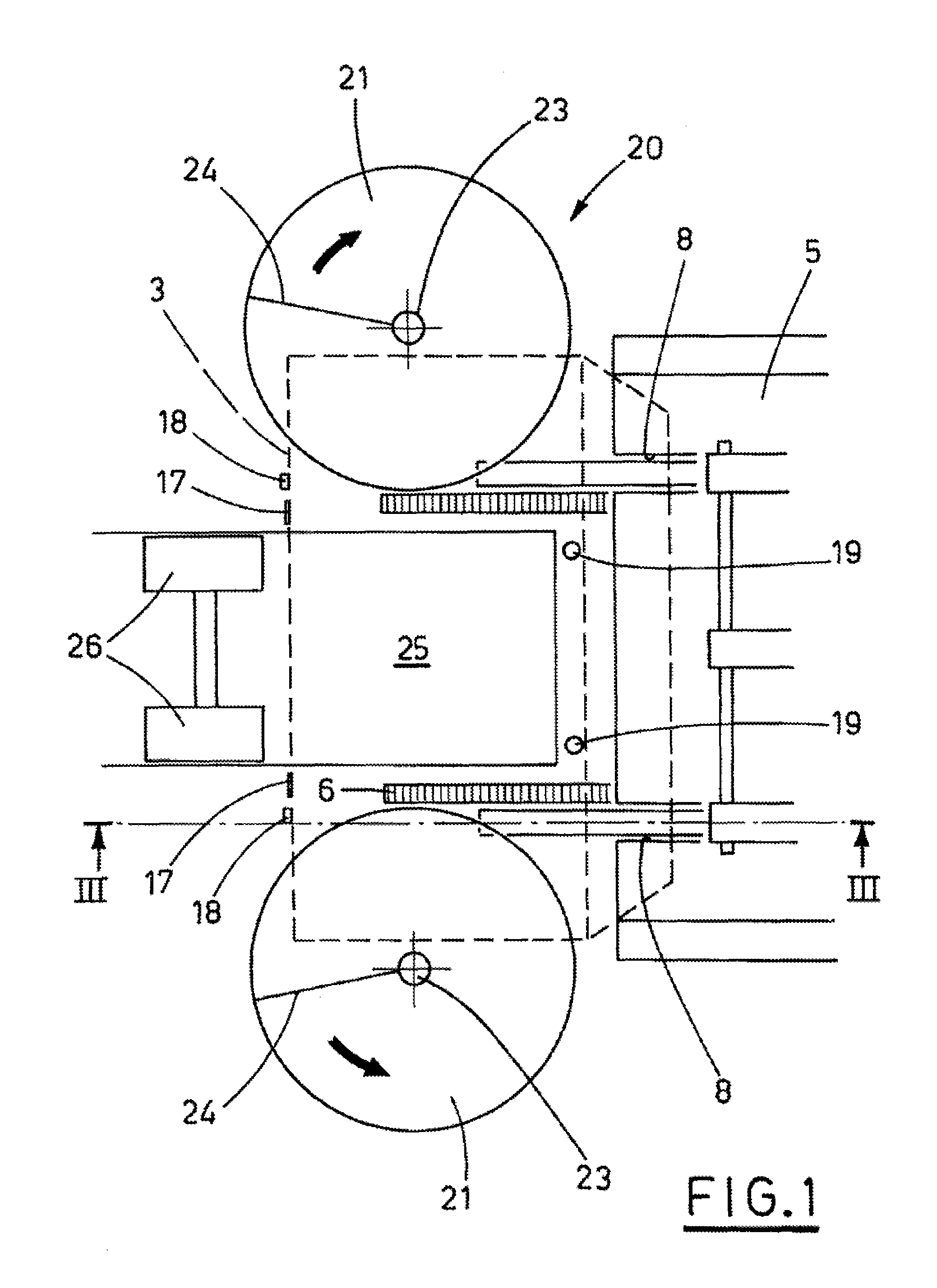
[0039]Pushing means 7, e.g. pairs of lugs or prongs, move along the sliding surface 5 in the direction indicated with the arrow A, as they are moved by a driving line 6, situated therebelow, including e.g. endless chains.

[0040]The lugs of the pushing means 7 protrude from longitudinal slots 8 made along the sliding surface 5, and rest with the bottom on suitable support means 9, aimed at keeping the pushing means 7 in a raised position.

[0041]The envelope filling station 1 is located just downstream of the sliding surface 5. The bottom of the filling sta...


PUM

PropertyMeasurementUnit
widthaaaaaaaaaa
speedaaaaaaaaaa
rotationaaaaaaaaaa

Abstract

An envelope filling machine for introducing sheets into envelopes includes a sliding surface, for transferring the sheets to an envelope filling station by means of pushing lugs, operated along the sliding surface. An envelope supplying conveyor supplies individual envelopes to the station placing them between vertical shafts of a pair of screws. The turns of the screws hold the sides of the envelopes and move each envelope downwards keeping the envelope separated from a subsequent envelope. When the envelope has come to rest on a conveyor belt placed between and under the screws, the lugs push the sheets into the envelope kept steady by movable stop strips yieldingly maintained by elastic means. When the sheets are fully inserted, the lugs push the envelope and force the movable strips to swing and let the filled envelope leave the envelope filling station.

Description

BACKGROUND OF THE INVENTION[0001]The present invention relates to an envelope filling machine, aimed in particular at introducing sheets into envelopes.DESCRIPTION OF THE PRIOR ART[0002]The development of the so-called “mailing” field, that includes sending sheet printed materials, such as letters, advertisement prints, brochures, magazines, and the like (in the following referred to as sheets) to a large number of different addressees, often entrusted to utility firms, creates the need of envelope filling machines, which can stuff envelopes at very high speeds.[0003]Some envelope filling machines form the envelopes from a paper sheet folded around the material to be mailed. Other envelope filling machines introduce the sheets into already formed envelopes. The empty envelopes are stacked within a storage area, such as a vertical magazine, from which they are taken and supplied one by one to an envelope filling station.[0004]The envelope magazine and the means used to supply the env...

Claims


Application Information

Patent Timeline
Patent Type & Authority Patents(United States)
IPC IPC(8): B65B43/26
CPCB43M3/045
Inventor PONTI, FRANCESCO
Owner CMC SRL
Why Eureka
Try Eureka