
Liquid discharge recording head and method for manufacturing same

a liquid discharge and recording head technology, applied in printing and other directions, can solve the problems of reducing the endurance and reliability of the recording head, the difficulty of mass production, and the inability to achieve mass production, so as to reduce the possibility of creating any void in the nozzle plate, reduce the thickness of the nozzle plate, and enhance production efficiency

Inactive Publication Date: 2009-01-13
CANON KK
View PDF7 Cites 15 Cited by
  • Summary
  • Abstract
  • Description
  • Claims
  • Application Information

AI Technical Summary

Benefits of technology

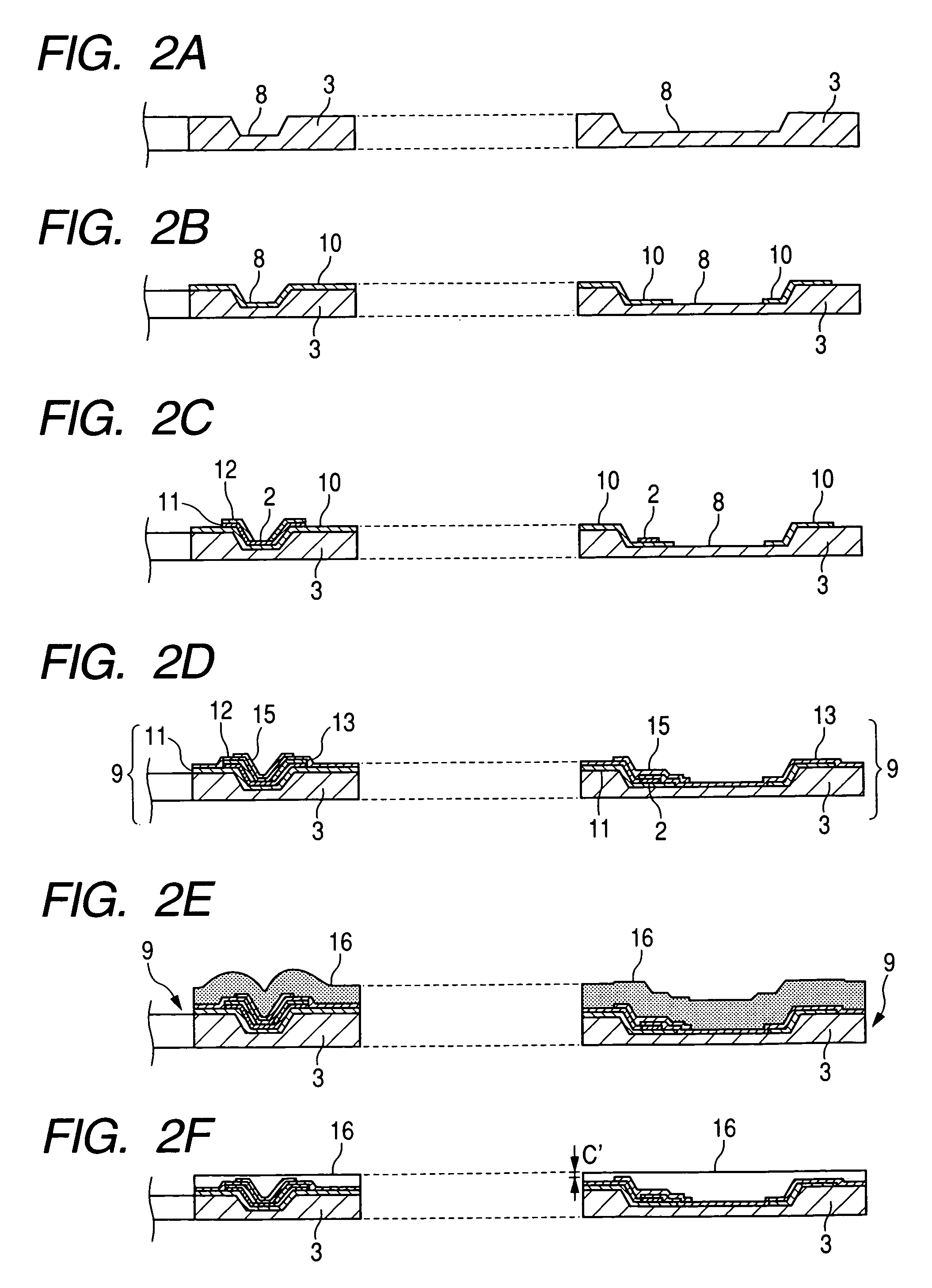
The present invention provides a method for manufacturing a liquid discharge recording head with a nozzle plate made of inorganic material, which reduces the thickness of the nozzle plate and increases production efficiency. The method includes steps for forming a recessed portion in the silicon substrate, adding a heat-insulative layer, a heating layer, a protective layer, a pattern layer, etching the nozzle plate layer, etching the silicon substrate, and removing the pattern layer. The resulting recording head has reduced inner stress, increased strength and reliability, and decreased possibility of peeling and breakage.

Problems solved by technology

However, the organic resin material has properties such as low mechanical strength, a low glass transition point, high thermal expansion rate and high moisture absorption expansion rate, and thus, due to such properties, there arise a problem that endurance and reliability of the recording head are reduced.
However, the organic resin material has properties such as low mechanical strength, a low glass transition point, high thermal expansion rate and high moisture absorption expansion rate, and thus, due to such properties, there arises a problem that endurance and reliability of the recording head are reduced.
However, the manufacturing method disclosed in the above-mentioned Japanese Patent Application Laid-Open No. 2001-287373 had the following problems.
Thus, the through-put of the film forming apparatus is considerably worsened, so that the mass production is hard to be achieved unless many of expensive film forming apparatuses are provided.
Further, in a case where a high density arrangement of nozzles is further developed, with the result that a gap between the pattern layers is more reduced, filling of the inorganic material into the gap is worsened.
As a result, there is a great possibility of generating voids in the nozzle plate.
On the other hand, if any void is tried to be prevented from being created in the nozzle plate, the degree of freedom for the designing will be greatly limited.
Further, the greater the thickness of the inorganic material layer, the greater inner stress, with the result that breakage is apt to be occurred in an interface between the layer and the silicon substrate.
Generally, the conventional manufacturing methods are expensive and have low through-put.

Method used


Image

  • Liquid discharge recording head and method for manufacturing same
  • Liquid discharge recording head and method for manufacturing same
  • Liquid discharge recording head and method for manufacturing same

Examples


Embodiment Construction

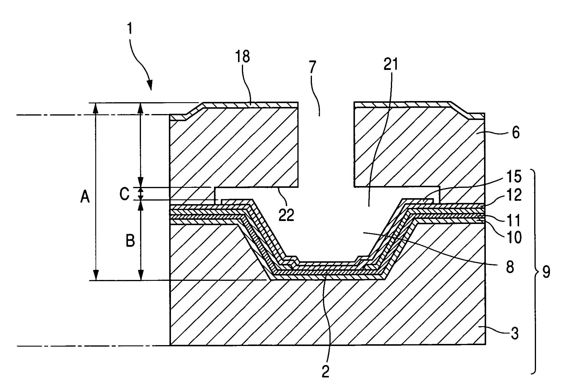
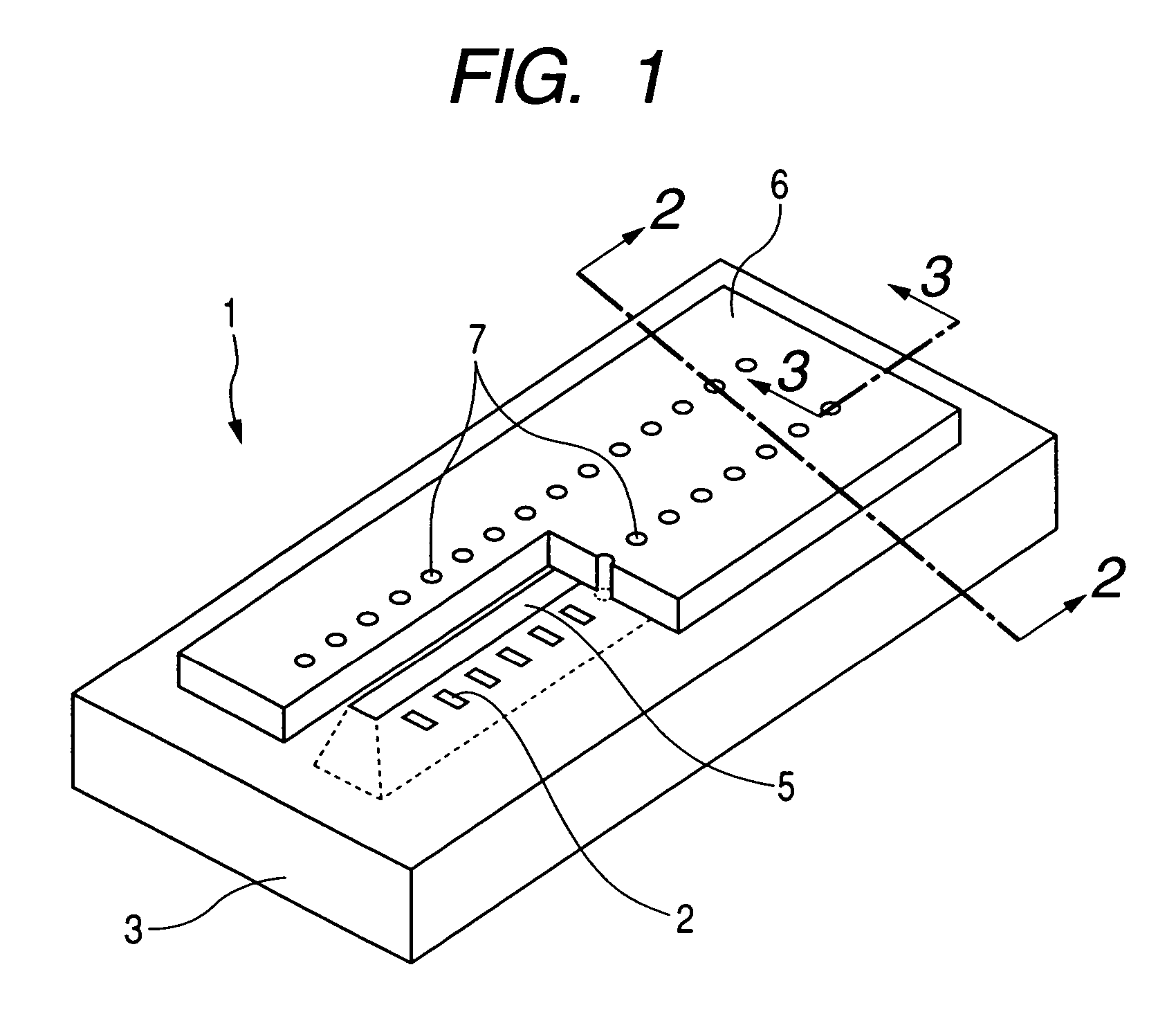
[0017]Now, an embodiment of a recording head according to the present invention will be explained with reference to the accompanying drawings. FIG. 1 is a schematic perspective view showing a recording head 1 according to this embodiment. The recording head 1 comprises a silicon substrate 3 on which heat generating resistant (or resistor) members 2 as discharge energy generating elements for generating energy for discharging liquid (ink) are formed in two rows with a predetermined pitch. An ink supply port 5 is elongated along a longitudinal direction of the silicon substrate 3 and is opened to the surface of the silicon substrate 3 between two rows of the heat generating resistant members. Further, on the front surface of the silicon substrate 3, discharge ports 7 opened above the respective heat generating resistant members 2 and a plurality of flow paths (not shown) for communicating the ink supply port 5 with the respective discharge port 7 are formed by a nozzle plate 6 consist...


PUM


Abstract

A liquid discharge recording head in which a nozzle plate is formed from inorganic material can be manufactured at low cost and with good through-put. In the liquid discharge recording head, a nozzle plate formed from inorganic material is stacked on a front surface of a silicon substrate including heat generating resistor members for generating energy for discharging liquid and an electric circuit for driving the heat generating resistor members. The liquid can be supplied from a liquid supply port extending through the silicon substrate to flow paths provided between the silicon substrate and the nozzle plate. Recessed portions having predetermined depths are formed in regions of the surface of the silicon substrate, where the flow paths are formed, and discharge ports are formed above the recessed portions.

Description

BACKGROUND OF THE INVENTION[0001]1. Field of the Invention[0002]The present invention relates to a liquid discharge recording head (also referred to merely as “recording head” hereinafter) for forming an image on a surface of a recording medium by discharging ink or other liquid toward the recording medium and a method for manufacturing such a head. Here, the wording “form an image” means that not only any meaningful image such as a character, a figure, a symbol or the like is formed, but also a particular meaningless image such as a geometric pattern or the like is formed.[0003]2. Related Background Art[0004]In conventional recording heads, liquid is supplied to a plurality of flow paths formed in one surface of a substrate via liquid supply ports extending through the substrate in a thickness-wise direction, and the liquid is supplied to corresponding discharge ports via the respective flow paths. In general, the flow paths and the discharge ports are formed by patterning of a fil...

Claims


Application Information

Patent Timeline
Patent Type & Authority Patents(United States)
IPC IPC(8): B41J2/05
CPCB41J2/14129B41J2/1603B41J2/1628B41J2/1629B41J2/1632B41J2/1635B41J2/1639B41J2/1642
Inventor FUJII, KENJIKOYAMA, SHUJIOSUMI, MASAKIYAMAMURO, JUNMURAYAMA, HIROYUKI
Owner CANON KK
Learn More