Arrangement and method for controlling a combustion engine

a technology of combustion engine and crankshaft, which is applied in the direction of electrical control, process and machine control, instruments, etc., can solve the problem of difficulty in controlling the self-ignition of the fuel mixture to the correct crankshaft angle, and achieve the effect of varying the effective compression ratio

Inactive Publication Date: 2009-01-13
SCANIA CV AB
View PDF8 Cites 0 Cited by
  • Summary
  • Abstract
  • Description
  • Claims
  • Application Information

AI Technical Summary

Benefits of technology

[0007]The object of the present invention is to provide an arrangement and a method for achieving functional control of the self-ignition of a combustion engine even when rapid shifts between different operating points are required.
[0008]This object is achieved with the arrangement which comprises an arrangement for controlling a combustion engine, wherein the combustion engine comprises a combustion chamber, a movable piston adapted to compressing a fuel mixture in the combustion chamber so as to cause self-ignition of the fuel mixture, a crankshaft driven by movements of the piston. at least one inlet valve of the combustion chamber and at least one exhaust valve of the combustion chamber, wherein the arrangement comprises a control unit operable for initiating at least one of closure and opening of at least one inlet valve and at least one exhaust valve at a crankshaft angle (ivc, ivo, evc) such that self-ignition of the fuel mixture occurs when the crankshaft is at substantially a desired crankshaft angle (SOCbör), the arrangement comprises a storage device adapted to storing relevant values of the crankshaft angle (ivc, ivo, evc) as a function of at least one operation-related parameter (n, τ) and a parameter-estimator operable for estimating values of the operation-related parameter (n, τ) during operation of the combustion engine. whereby the control unit is adapted to initiating the at least one of closure and opening of the inlet valve and the exhaust valve with the stored value of the crankshaft angle (ivc, ivo, evc) which corresponds to the estimated current value of the operation-related parameter (n, τ). With advantage, storage means, i.e., a storage device are used in the form of, for example, cards which comprise relationships between one or more operation-related parameters and relevant values of crankshaft angles at which the inlet valve and / or the exhaust valve have to be opened or closed if self-ignition is to take place at a desired crankshaft angle. Such stored cards and information about current values of operation-related parameters can be used to provide information about a relevant value of crankshaft angle at which the valve adjustment needs to be effected close to each combustion process. It is thus possible to provide rapidly adjustable control of a combustion engine even when rapid shifts between different operating points are required.
[0009]According to a preferred embodiment of the present invention, said storage means are adapted to storing values of said crankshaft angle and the operation-related parameter when the crankshaft is at a predetermined rotational position. Said predetermined rotational position needs to be close to the crankshaft angle at which self-ignition occurs but at a well-selected distance before self-ignition commences. With advantage, said predetermined rotational position of the crankshaft is within the range 8° to 12° before it reaches a rotational position which corresponds to the piston's top dead centre position at which the self-ignition of the fuel mixture substantially occurs. Within this range it is possible to provide a predetermined crankshaft angle which is close to the self-ignition but at a clear distance from the start of the self-ignition process.
[0011]According to a preferred embodiment of the present invention, the arrangement comprises detection means adapted to detecting when the actual self-ignition of the fuel mixture commences. The start of the combustion process may for example be detected by means of the aforesaid pressure sensor which substantially continuously detects the pressure in the combustion chamber. In this case the start of the combustion process can be detected substantially directly when a pressure rise due to the combustion process is detected. Alternatively, a crankshaft angle may be detected at which, for example, half of the fuel has been consumed. Thereafter the start of the combustion process can be calculated on the basis of information about parameters such as, inter alia, lambda λ. The arrangement may comprise feedback means adapted to comparing the actual crankshaft angle for self-ignition with the desired value for self-ignition, in which case the control unit is adapted to controlling the self-ignition of the next combustion process on the basis of this comparison. Knowledge of this difference makes it possible to effect an adjustment of the next combustion process so that the influence of control errors and the like is reduced.
[0013]With advantage, the control unit is adapted to initiating, in a second load range, closure of the inlet valve at a crankshaft angle in such a way that it is possible to vary the effective compression ratio in the combustion chamber. This strategy is used for richer than ideal fuel mixtures. Using these two strategies which are thus mutually adjacent makes it possible to provide control of a combustion engine over a continuous relatively large load range.
[0014]The object of the invention is also achieved with a method comprising a control unit operable for initiating at least one of closure and opening of at least one inlet valve and at least one exhaust valve at a crankshaft angle (ivc, ivo, evc) such that self-ignition of the fuel mixture occurs when the crankshaft is at substantially a desired crankshaft angle (SOCbor). The arrangement comprises a storage device adapted to storing relevant values of the crankshaft angle (ivc, ivo, evc) as a function of at least one operation-related parameter (n, τ) and a parameter-estimator operable for estimating values of the operation-related parameter (n, τ) during operation of the combustion engine. The control unit is adapted to initiating the at least one of closure and opening of the inlet valve and the exhaust valve with the stored value of the crankshaft angle (ivc, ivo, evc) which corresponds to the estimated current value of the operation-related parameter (n, τ). Storing relevant values of the crankshaft angle as a function of at least one operation-related parameter makes it relatively easy to provide a relevant value of crankshaft angle at which the valve adjustment needs to be effected during each cycle of a combustion engine's combustion processes. It is thus possible to provide a control which quickly adapts to prevailing circumstances so that self-ignition of the combustion engine is substantially always achieved when the crankshaft is at a substantially optimum rotational angle.

Problems solved by technology

One reason why HCCI engines are not used conventionally to any great extent is that it is difficult to control the self-ignition of the fuel mixture to a correct crankshaft angle.
A difficulty of such valve control strategies is that they entail the valve having to be controlled quickly and with good precision between substantially each cycle of combustion processes so that the self-ignition in the HCCI engine occurs at a substantially optimum crankshaft angle even when rapid shifts between different operating points are required.

Method used


Image

  • Arrangement and method for controlling a combustion engine
  • Arrangement and method for controlling a combustion engine
  • Arrangement and method for controlling a combustion engine

Examples


Embodiment Construction

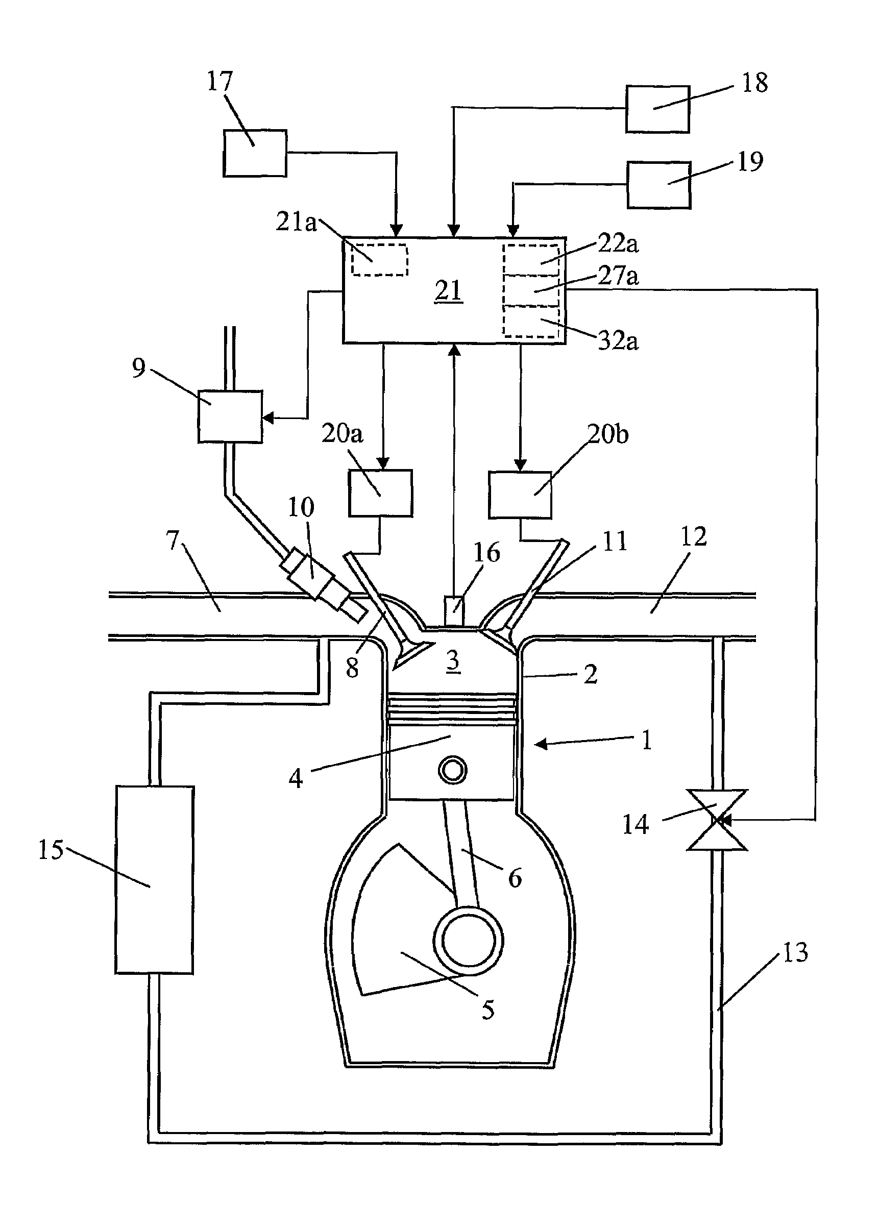
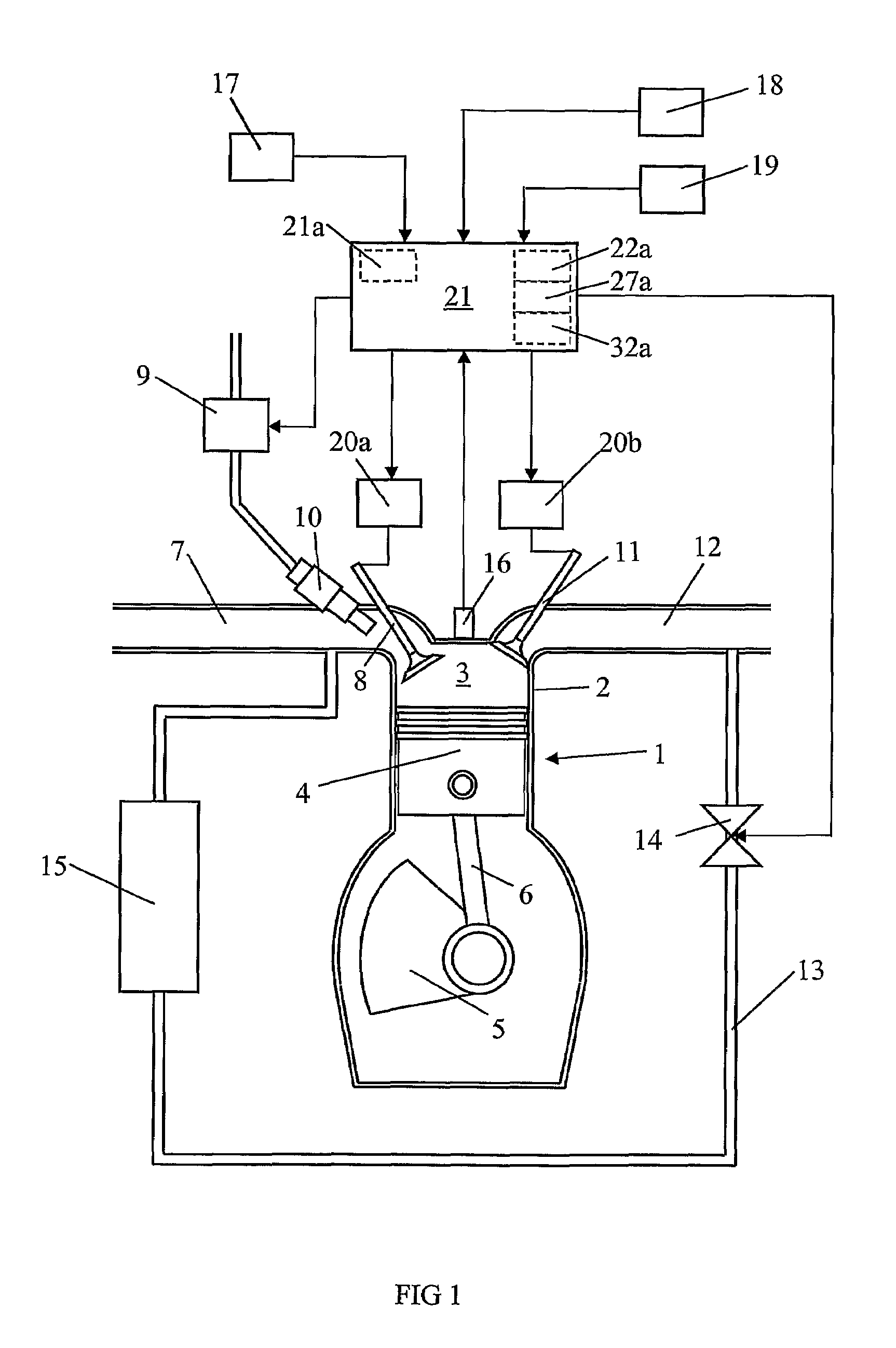
[0024]FIG. 1 depicts an arrangement for controlling a four-stroke combustion engine 1 of the type in which a homogeneous mixture of fuel and air is compressed until self-ignition of the mixture is caused by the heat developed during the compression. Such an engine 1 is usually called an HCCI (homogeneous charge compression ignition) engine. An HCCI engine may be regarded as a combination of an Otto engine and a diesel engine. The engine 1 is depicted here with one cylinder 2 but may of course have substantially any desired number of such cylinders 2. The engine 1 comprises a combustion chamber 3 which is bounded downwards in the cylinder 2 by a movable piston 4. The piston is connected to a crankshaft 5 via a connecting rod 6. The motion of the piston 4 in the cylinder 2 converts to rotary motion of the crankshaft 5.

[0025]When the piston 4 moves downwards in the cylinder 2 and an inlet valve 8 is open, air is drawn into the expanding combustion chamber 3 via an inlet line 7. At the ...


PUM


Abstract

An arrangement, a computer-readable medium and a method for controlling an HCCI (homogenous charge compression ignition) engine are disclosed. The arrangement comprises a control unit for initiating closure and / or opening of the inlet valve and / or the exhaust valve at a current crankshaft angle in such a way that self-ignition of the fuel mixture occurs when the crankshaft is at a target crankshaft angle. The arrangement comprises cards for storing relevant values of the current crankshaft angle as a function of at least one operation-related parameter such as engine speed, temperature and pressure, and an estimator estimating values of the operation-related parameter during operation of the combustion engine. The control unit can adjust the inlet valve and / or the exhaust valve depending on the stored value of the current crankshaft angle.

Description

CROSS REFERENCE TO RELATED APPLICATION[0001]The present application is a 35 U.S.C. §§ 371 national phase conversion of PCT / SE2005 / 0015 19, filed Oct. 13, 2005, which claims priority of Swedish Application No. 0402534-2, filed Oct. 20, 2004. The PCT International Application was published in the English language.[0002]The present invention relates to an arrangement and a method for controlling a combustion engine by controlling operation of an inlet valve or an outlet valve of the combustion chamber for controlling ignition.[0003]One type of such combustion engines is called HCCI (homogeneous charge compression ignition) engines, which may be regarded as a combination of an Otto engine and a diesel engine. In HCCI engines, a homogeneous mixture of fuel and air is compressed in a combustion chamber until self-ignition of the fuel mixture occurs. Advantages of HCCI engines are that they produce low discharges of nitrogen oxides NOx and soot particles while at the same time having a hig...

Claims


Application Information

Patent Timeline
Patent Type & Authority Patents(United States)
IPC IPC(8): F02D28/00F02DF02D13/02F02D15/04F02D19/06F02D41/30
CPCF02D13/0207F02D13/0265F02D35/023F02D35/028F02D41/006F02D41/3035F02D41/0052F02B1/12F02D15/04Y02T10/18F02D2041/001F02M25/07Y02T10/128Y02T10/47F02M26/00Y02T10/12Y02T10/40F02D13/02F02D41/26F02D43/04
Inventor AGRELL, FREDRIK
Owner SCANIA CV AB
Why Eureka
Try Eureka