
Continuous annealing unit and circulating temperature control device for aging section of continuous annealing unit

A technology of cyclic temperature control and continuous withdrawal unit, which is used in the improvement of process efficiency, heat treatment process control, furnace type and other directions, can solve the problems of prolongation, furnace thermal inertia fluctuation, environmental pollution, etc. The temperature control is fast and effective, and the effect of improving the reflection sensitivity

Active Publication Date: 2014-02-05
PANGANG GRP XICHANG STEEL & VANADIUM CO LTD
View PDF5 Cites 0 Cited by
  • Summary
  • Abstract
  • Description
  • Claims
  • Application Information

AI Technical Summary

Problems solved by technology

[0004] Problems with the prior art include: Complementary N 2 、H 2 The pipeline of such gas medium is generally designed with a diameter of Φ50mm, and its replenishment amount per unit time is limited, and it prolongs the replenishment of N 2 、H 2 The time required to wait for the gas medium
It is impossible to solve the above problem by selecting a pipe with a larger diameter, because the large pipe diameter will cause fluctuations in the thermal inertia of the furnace, which will affect the thermal energy balance and pressure balance of the furnace connected to the OAS section, resulting in a long time for the production of transitional products. Defects such as an increase in the amount of waste and defective products generated
In addition, if the supplementary N 2 、H 2 and other gaseous media are discharged naturally, which not only causes environmental pollution, but also causes N 2 、H 2 The free consumption of such gaseous media increases the energy consumption cost of OAS section operation

Method used


Image

  • Continuous annealing unit and circulating temperature control device for aging section of continuous annealing unit

Examples


Embodiment Construction

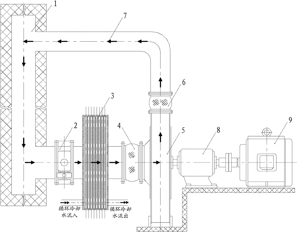
[0021] Hereinafter, exemplary embodiments of the present invention will be described in detail with reference to the accompanying drawings. The present invention utilizes the mode of absorbing the hot gas medium from the bottom of the furnace in the aging section, and then injecting the cold gas medium into the top of the furnace in the aging section, making full use of the sinking characteristics of the cold gas medium, and rapidly making the atmosphere temperature in the furnace in the aging section reach the required level temperature conditions.

[0022] figure 1 It is a schematic diagram of the circulation temperature control device of the aging section of the continuous annealing unit according to an exemplary embodiment of the present invention, and the arrows in the figure indicate the flow direction. According to the circulation temperature control device of the aging section of the continuous annealing unit of the present invention, it includes a pipeline 7, a valve...


PUM


Abstract

The invention discloses a circulating temperature control device for the aging section of a continuous annealing unit. The circulating temperature control device comprises a pipeline, a valve, a heat exchanger, a first expansion joint and a blower, wherein one end of the pipeline is communicated with the bottom of a firebox on the aging section; the other end of the pipeline is communicated with the top of the firebox on the aging section; the valve, the heat exchanger, the first expansion joint and the blower are arranged on the pipeline in sequence; the valve is adjacent to the bottom of the valve firebox on the aging section; and the heat exchanger is used for controlling the temperature of a gaseous medium in the aging section of the continuous annealing unit in a heat exchange manner. According to the requirements of production, the temperature in the firebox can be adjusted and controlled fast, and the consumption of the gaseous medium is greatly reduced through the cyclic utilization of the gaseous medium. Moreover, the temperature of the gaseous medium can be controlled fast and effectively; the production of transitional materials is effectively reduced; the production rhythm is accelerated; and the circulating temperature control device has a wide potentiality in the technical popularization of an annealing furnace in the continuous annealing unit.

Description

technical field [0001] The invention relates to the field of heat treatment equipment for rolling steel, more specifically, to a cycle temperature control device for the aging section of a continuous annealing unit and a continuous annealing unit including the cycle temperature control device. Background technique [0002] In the continuous annealing unit, the annealing furnace heat-treats the steel strip. The annealing furnace includes a preheating section, a heating section, a soaking section, a slow cooling section, a fast cooling section, an aging section (hereinafter referred to as the OAS section), a final cooling section and a water quenching tank. The main function of the OAS section is in the N 2 、H 2 Under the gas medium, keep the strip steel at a certain temperature for a certain period of time, speed up the aging efficiency of the strip steel, and make the strip steel achieve the required internal mechanical properties. [0003] During the aging treatment of st...

Claims


Application Information

Patent Timeline
Patent Type & Authority Patents(China)
IPC IPC(8): C21D9/56C21D1/26C21D11/00
CPCY02P10/20
Inventor 雷华北汤伟马军
Owner PANGANG GRP XICHANG STEEL & VANADIUM CO LTD
Learn More