Drum washing machine
a drum and washing machine technology, applied in the field of drum washing machines, can solve the problems of not always agreeing two critical speeds, and achieve the effect of high accuracy
- Summary
- Abstract
- Description
- Claims
- Application Information
AI Technical Summary
Benefits of technology
Problems solved by technology
Method used
Image
Examples
first embodiment
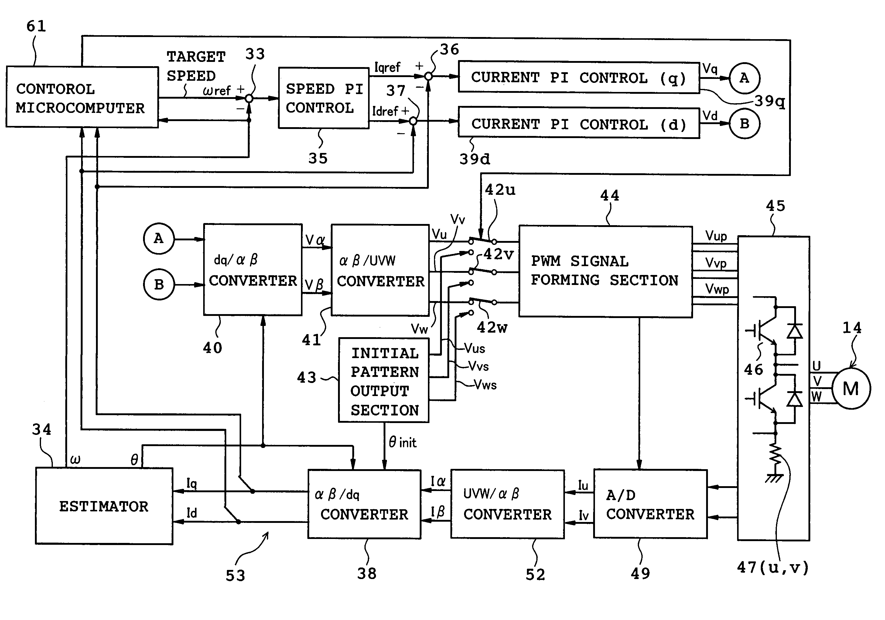
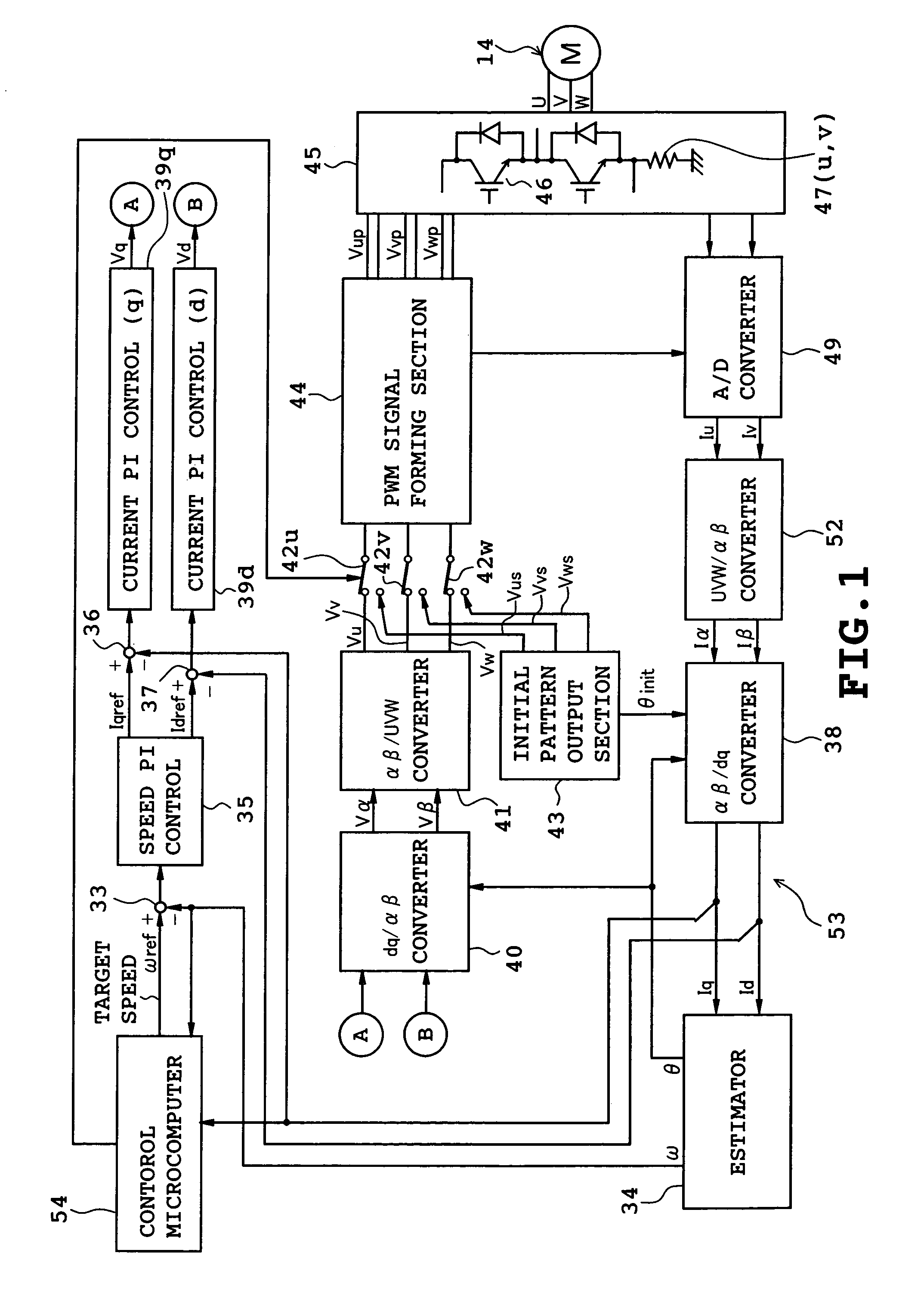
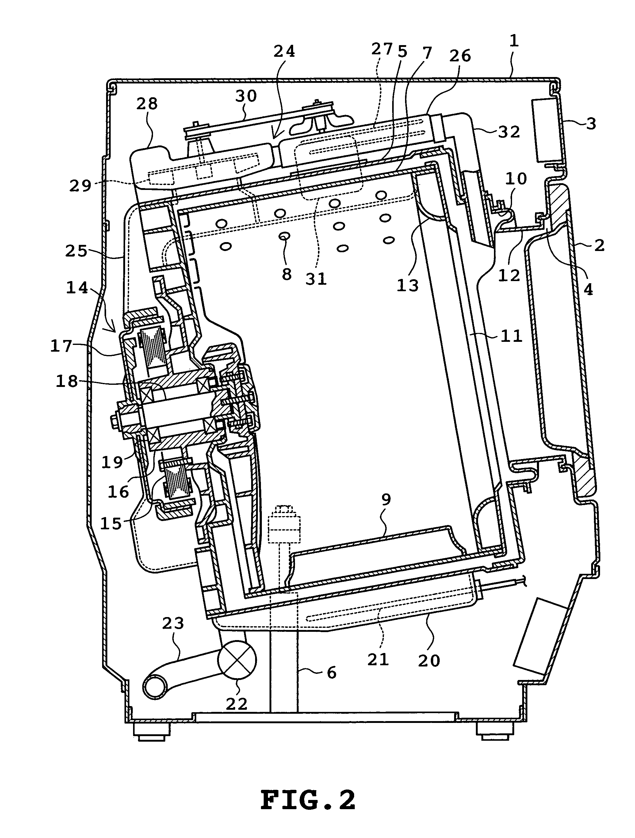
[0028]A first embodiment of the present invention will be described with reference to FIGS. 1 to 9. Referring to FIG. 2, an overall construction of the drum washing machine is shown. The drum washing machine comprises an outer cabinet 1 serving as an outer shell of the drum washing machine. The outer cabinet 1 is provided with a door 2 mounted on the central front thereof and an operation panel 3 mounted on the upper front thereof. The operation panel 3 includes a number of switches and display sections none of which are shown. The door 2 closes and opens an access opening 4 formed in the central front of the outer cabinet 1. Laundry is put into and taken out of a drum 7 through the access opening 4.
[0029]A cylindrical water tub 5 is disposed in the outer cabinet 1. The water tub 5 has an axis extending substantially horizontally in the back-and-forth direction so that a rear portion thereof is inclined downward. The water tub 5 is elastically supported by elastically supporting mea...
second embodiment
[0056]FIGS. 8 and 9 illustrate a second embodiment of the invention. Identical or similar parts in the second embodiment are labeled by the same reference symbols as those in the first embodiment. Only the difference of the second embodiment from the first embodiment will be described in the following. The arrangement of the second embodiment is basically the same as that of the first embodiment, but the software contents for the control microcomputer in the second embodiment differ from those in the first embodiment.
[0057]In the second embodiment, the rotational speed of the drum 7 is once increased to the upper reference speed Na (step S21) and thereafter, the rotational speed is gradually decreased toward the lower reference speed Nb (maximum period Tk) (step S22). Subsequently, steps S3 to S5 and S8 to S13 are executed in the same manner as in the first embodiment. Further, when determining in the negative (NO) at step S5, the control microcomputer 54 carries out steps S16 and S...
third embodiment
[0061]FIGS. 10 to 15 illustrate a third embodiment of the invention. In the third embodiment, the d-axis current in the vector control is also used for the purpose of estimating the laundry weight.
[0062]Firstly, the principles of the estimation will be described with reference to FIGS. 14 and 15. FIG. 14 is a graph on which are plotted determination values measured when the temperature of the motor 14 (mainly the winding temperature) is changed and the drum 17 is rotated under no load condition, the condition of a 2.2 kg artificial load, and the condition of a 5.3 kg artificial load. Regarding each condition, measured points are divided into two groups. The lower temperature side group indicates the case where the room temperature is at 14° C., whereas the higher temperature side group indicates the case where the room temperature is at 26° C. FIG. 14 shows that a determination value tends to become larger under the same load condition as the temperature of the motor 14 rises. This ...
PUM
 Abstract
Description
Claims
Application Information
 - R&D
- Intellectual Property
- Life Sciences
- Materials
- Tech Scout
- Unparalleled Data Quality
- Higher Quality Content
- 60% Fewer Hallucinations
Browse by: Latest US Patents, China's latest patents, Technical Efficacy Thesaurus, Application Domain, Technology Topic, Popular Technical Reports.
© 2025 PatSnap. All rights reserved.Legal|Privacy policy|Modern Slavery Act Transparency Statement|Sitemap|About US| Contact US: help@patsnap.com


