
Methods of applying substrate bias to SOI CMOS circuits

a substrate bias and circuit technology, applied in the direction of basic electric elements, electrical equipment, semiconductor devices, etc., can solve the problems of generating imbalances subsequently, determining the threshold voltage imbalance,

Inactive Publication Date: 2009-01-20
GLOBALFOUNDRIES INC
View PDF10 Cites 13 Cited by
  • Summary
  • Abstract
  • Description
  • Claims
  • Application Information

AI Technical Summary

Benefits of technology

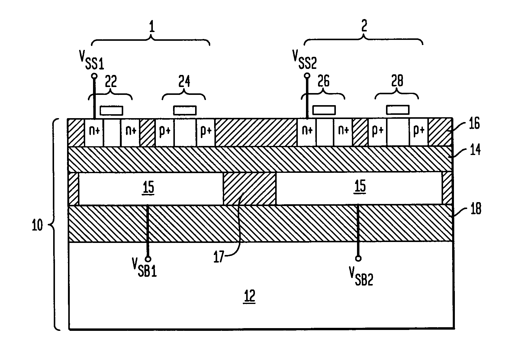
[0008]b. applying a substrate bias voltage to the at least one CMOS circuit so as to reduce the difference between the threshold voltage of the at least one n-FET and the threshold voltage of the at least one p-FET by at least 5%.
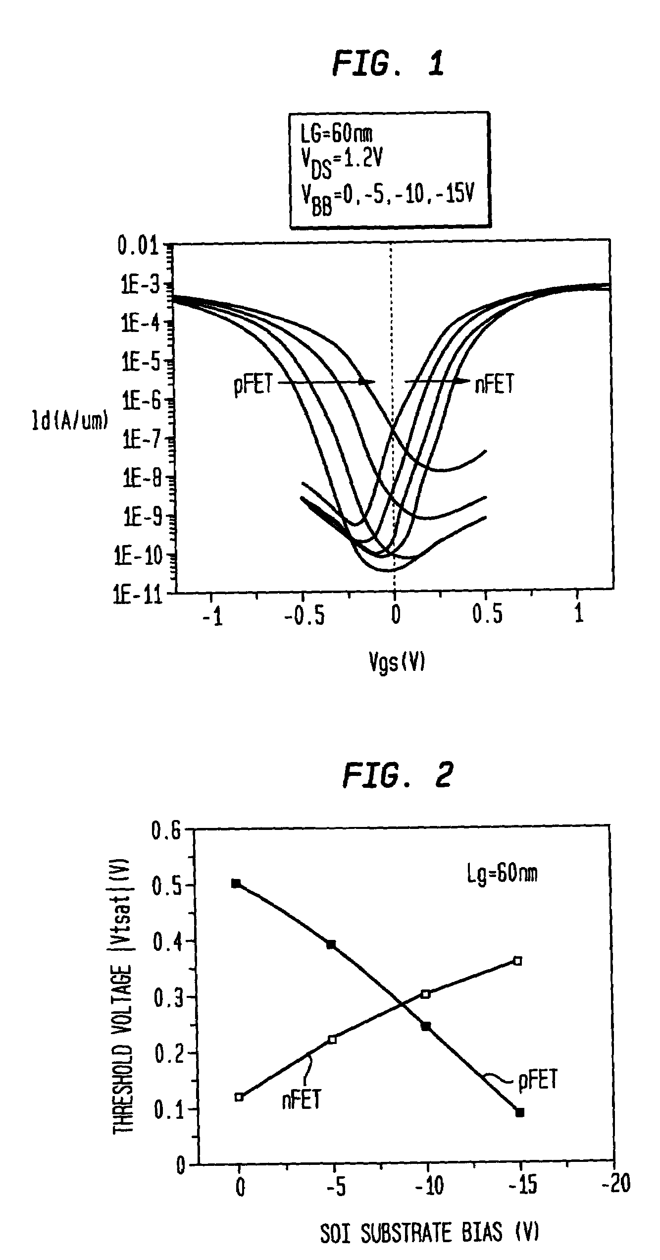
[0010]Preferably, the substrate bias voltage applied to the CMOS circuit functions to reduce the threshold voltage difference between the n-FET and the p-FET by at least 20%, more preferably by at least 50%, and most preferably by at least 95%.
[0015]b. at least one voltage applicator for applying a substrate bias voltage to the at least one CMOS circuit so as to reduce the difference between the threshold voltage of the at least one n-FET and the threshold voltage of the at least one p-FET by at least 5%.

Problems solved by technology

Although differentially doped polysilicon electrodes can be used in place of metal or metal silicide electrodes to reduce the threshold voltage differential between n-FETs and p-FETs, the process variations for n-FETs and p-FETs may affect the threshold voltages of the n-FETs and p-FETs differently, therefore still resulting in a certain degree of threshold voltage imbalance therebetween.
Thus, even if the threshold voltages are balanced at room temperature, imbalance may be generated subsequently during operation, because the operating temperature of the integrated circuit (IC) chip is typically 60-80 degrees higher than room temperature.

Method used


Image

  • Methods of applying substrate bias to SOI CMOS circuits
  • Methods of applying substrate bias to SOI CMOS circuits
  • Methods of applying substrate bias to SOI CMOS circuits

Examples


Embodiment Construction

[0025]In the following description, numerous specific details are set forth, such as particular structures, components, materials, dimensions, processing steps and techniques, in order to provide a thorough understanding of the present invention. However, it will be appreciated by one of ordinary skill in the art that the invention may be practiced without these specific details. In other instances, well-known structures or processing steps have not been described in detail in order to avoid obscuring the invention.

[0026]It will be understood that when an element as a layer, region or substrate is referred to as being “on” another element, it can be directly on the other element or intervening elements may also be present. In contrast, when an element is referred to as being “directly on” another element, there are no intervening elements present. It will also be understood that when an element is referred to as being “connected” or “coupled” to another element, it can be directly c...


PUM


Abstract

The present invention relates to methods for reducing the threshold voltage difference between an n-type field effect transistor (n-FET) and a p-type field effect transistor (p-FET) in a complementary metal-oxide-semiconductor (CMOS) circuit located on a silicon-on-insulator (SOI) substrate. Specifically, a substrate bias voltage is applied to the CMOS circuit for differentially adjusting the threshold voltages of the n-FET and the p-FET. For example, a positive substrate bias voltage can be used to reduce the threshold voltage of the n-FET but increase that of the p-FET, while a negative substrate bias voltage can be used to increase the threshold voltage of the n-FET but reduce that of the p-FET. Further, two or more substrate bias voltages of different magnitudes and / or directions can be used for differentially adjusting the n-FET and p-FET threshold voltages in two or more different CMOS circuits or groups of CMOS circuits.

Description

FIELD OF THE INVENTION[0001]The present invention relates to methods and devices for reducing the threshold voltage difference between n-type field effect transistors (n-FETs) and p-type field effect transistors (p-FETs) in complementary metal-oxide-semiconductor (CMOS) circuits fabricated on semiconductor-on-insulator (SOI) substrates.BACKGROUND OF THE INVENTION[0002]In CMOS circuits, it is desirable to tune the threshold voltages of the n-FET devices and the p-FET devices to achieve substantially the same magnitude, which provides a balance between the n-FET and p-FET drive currents and, in turn, leads to improved device performance and circuit speed.[0003]However, actual n-FET and p-FET threshold voltages in a CMOS circuit can be different due to various reasons. For example, if the n-FETs and the p-FETs contain metal or metal silicide gate electrodes, their threshold voltages will be significantly different, because the work function of metal or metal silicide is asymmetric with...

Claims


Application Information

Patent Timeline
Patent Type & Authority Patents(United States)
IPC IPC(8): H01L21/00
CPCH01L21/84H01L27/1203H01L29/78648
Inventor CAI, JINHAENSCH, WILFRIED E.NING, TAK H.
Owner GLOBALFOUNDRIES INC
Learn More