Hand-held tester and method for local area network cabling

a local area network and tester technology, applied in data switching networks, instruments, frequency-division multiplexes, etc., can solve the problems of link failure, limited test life of adapters, technician work, etc., and achieve the effect of low cost and easy operation

Inactive Publication Date: 2009-01-20
IDEAL IND NETWORKS LTD
View PDF4 Cites 134 Cited by
  • Summary
  • Abstract
  • Description
  • Claims
  • Application Information

AI Technical Summary

Benefits of technology

[0042]Preparatory to a description of the method of the present invention, a discussion of phase needs to be presented. The capability of phase measurement is a key attribute of the LAN tester of the present invention. That is, in addition to magnitude, the hand-held LAN tester of this invention can measure phase. This capability permits the tester to set a measurement reference plane at one specified point along the LAN link to be measured. The original calibration reference plane may be set at a point along the link at a point, which is easy to set, measure, define and implement.
[0043]Phase also allows the tester to easily move this original calibration reference plane and all of its associated LAN link measurements to another, new, reference plane location at any time during the LAN link testing. Specifically, with phase information, a display end and remote end can each move the phase reference plane from within the channel link adapter printed circuit board, through the mated pair of connectors at the CLA output and anywhere down the length of the patch cord, and up to the mated pair of connectors at the wall jack, in any of the four possible locations as shown in FIG. 9. Movement of the phase reference plane enables the tester of this invention to use a channel link adapter and low cost patch cord to perform permanent link measurements.

Problems solved by technology

If there are links that fail, the technician must re-test, and often replace connectors that have been incorrectly or improperly installed.
If not, then the link fails and the technician must work on the failed link, as required, until it passes.
2. Permanent Link Testing Lifetime: Permanent link adapters have a limited test lifetime due to mechanical flexing of the patch cord as it enters the PLA housing.
5. PLA Cost: The PLA's can be a costly item for the installers, often $400 or more for a set of two.
If the LAN cabling installation testing company has several installers, each requiring several different sets of vendor specific PLA's, this overhead item can be rather costly.
The measured cross talk or lack of isolation between conductor pairs within the PLA connection circuit board becomes a serious issue as frequencies increase.
When the isolation degrades beyond a certain level, the LAN tester cannot measure the cabling pair-to-pair isolation because it cannot “see” past its own PLA generated crosstalk.
7. PLA Reference Plane Calibration: The last issue with permanent link adapters is that of the measurement reference plane location.
The connector mounted on the printed circuit board inside the CLA eventually wears out as the cladding on the contacts wears off.
Nevertheless, the testing lifetime for the channel link adapter is considerably longer than that for the permanent link adapter.
7. CLA Reference Plane Calibration: The last issue with channel link adapters is also that of the measurement reference plane location.
From the preceding discussion, when compared to channel link adapters, permanent link measurements require the use of a separate set of permanent link adapters, which add an undesirable set of costs in terms of: 1) the permanent link adapters themselves; 2) the number of dedicated PLA sets; and 3) limited PLA test lifetime due to patch cord flexure failure.
Permanent link adapters also have more problems with minimizing pair-to-pair crosstalk when compared to channel link adapters.

Method used


Image

  • Hand-held tester and method for local area network cabling
  • Hand-held tester and method for local area network cabling
  • Hand-held tester and method for local area network cabling

Examples


Embodiment Construction

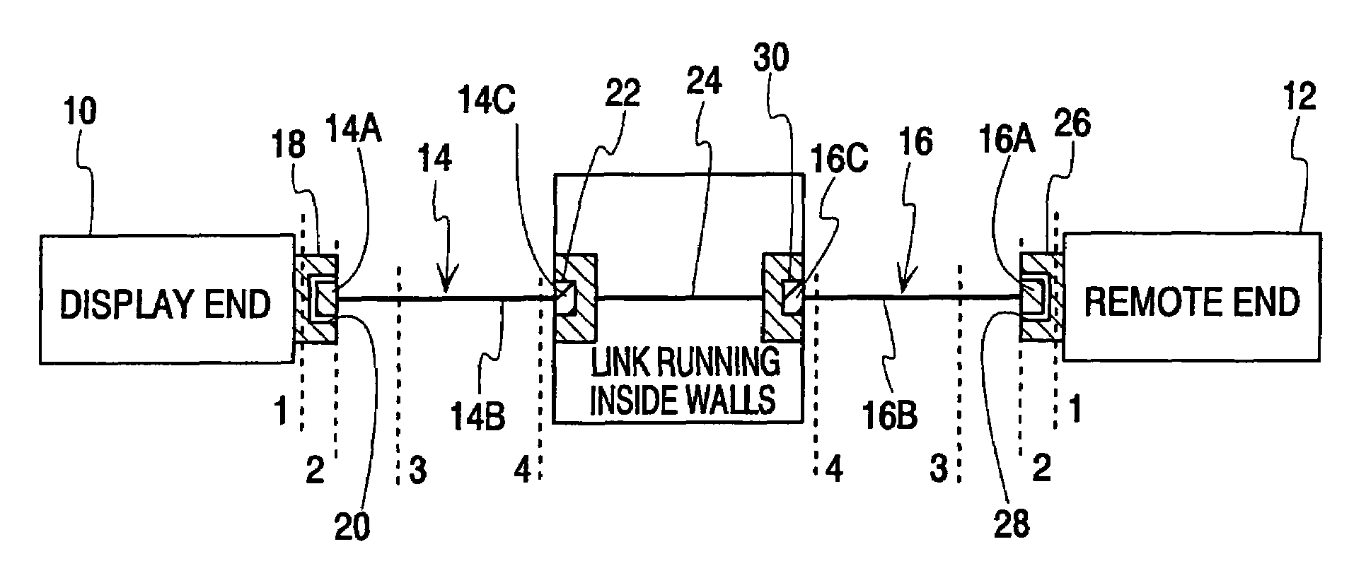
[0066]A schematic representation of the LAN testing system of the present invention is shown in FIG. 9. The testing systems includes a hand-held display unit 10, a hand-held remote unit 12 and first and second patch cords 14 and 16. Each patch cord comprises a first plug 14A, 16A at one end, the actual cable 14B, 16B and a second plug 14C, 16C at the other end. The display unit 10 has a channel link adapter board 18 on which is mounted a first connector jack 20. The jack is exposed to the exterior of the display unit. Jack 20 can receive the plug 14A or 16A of a patch cord to form a first mated connector pair. When shooting a link, the other plug 14C, 16C of the patch cord mates with a wall jack 22 attached to the link 24 running inside the walls. The remote unit 14 similarly has a channel link adapter board 26 on which is mounted a second connector jack 28. Both of the connectors 20 and 28 are preferably right-angle connectors with appropriate pair-to-pair isolation. An RJ-45 jack ...


PUM


Abstract

A LAN tester has display and remote units each having a connector jack attached to an adapter board for connection to the plug of a patch cord. Both the display and remote units have circuits which are capable of measuring the phase between a drive signal voltage and the corresponding coupled or reflected signal due to the drive signal. Scattering parameters for the mated connector pairs and the patch cord itself are measured during a field calibration. A computer in one or both of the tester units stores the measured scattering parameters and uses the scattering parameters to move the reference plane to any desired location along the patch cord. Channel link or permanent link tests can be conducted using the same equipment.

Description

CROSS REFERENCE TO RELATED APPLICATION[0001]This is a continuation-in-part of application Ser. No. 10 / 317,555 filed Dec. 12, 2002 now U.S. Pat. No. 6,847,213.BACKGROUND OF THE INVENTION[0002]Local area network (LAN) cabling is used to connect equipment such as personal computers, printers and fax machines that pass information between them using high-speed digital signals. This type of high performance cabling is sometimes referred to as telecommunications cable. Since an office contains many computers, computer file servers, printers, and fax machines, the LAN cabling interconnects all of this equipment into a communications network. LAN cabling has been designed to support telecommunication between all of the individual elements of the network.[0003]FIG. 1 shows an example of LAN cabling, in a simplified drawing. FIG. 1 shows how the LAN cabling, most of which runs within the building walls, is used to connect the personal computer 1 at someone's desk to the file server 2 in the t...

Claims


Application Information

Patent Timeline
Patent Type & Authority Patents(United States)
IPC IPC(8): G01R19/00G01R27/02G01R31/02G01R35/00H04L12/24H04L12/26
CPCH04B3/462H04B3/466H04L12/2697H04L41/26H04L43/50
Inventor RENKEN, GERALD W.DAVIS, KEITH H.PIVONKA, EDWARD
Owner IDEAL IND NETWORKS LTD
Why Eureka
Try Eureka