
Multi-pulse heterodyne sub-carrier interrogation of interferometric sensors

a multi-pulse heterodyne and interferometer technology, applied in the direction of converting sensor output, electromagnetic transmission, transmission, etc., can solve the imbalance of the time delay difference between the two paths of the sensor, the detection of interference signals, modulation frequency, etc., to improve the signal-to-noise ratio and increase the allowable interrogation pulse duty cycle

Active Publication Date: 2009-01-20
OPTOPLAN
View PDF115 Cites 10 Cited by
  • Summary
  • Abstract
  • Description
  • Claims
  • Application Information

AI Technical Summary

Benefits of technology

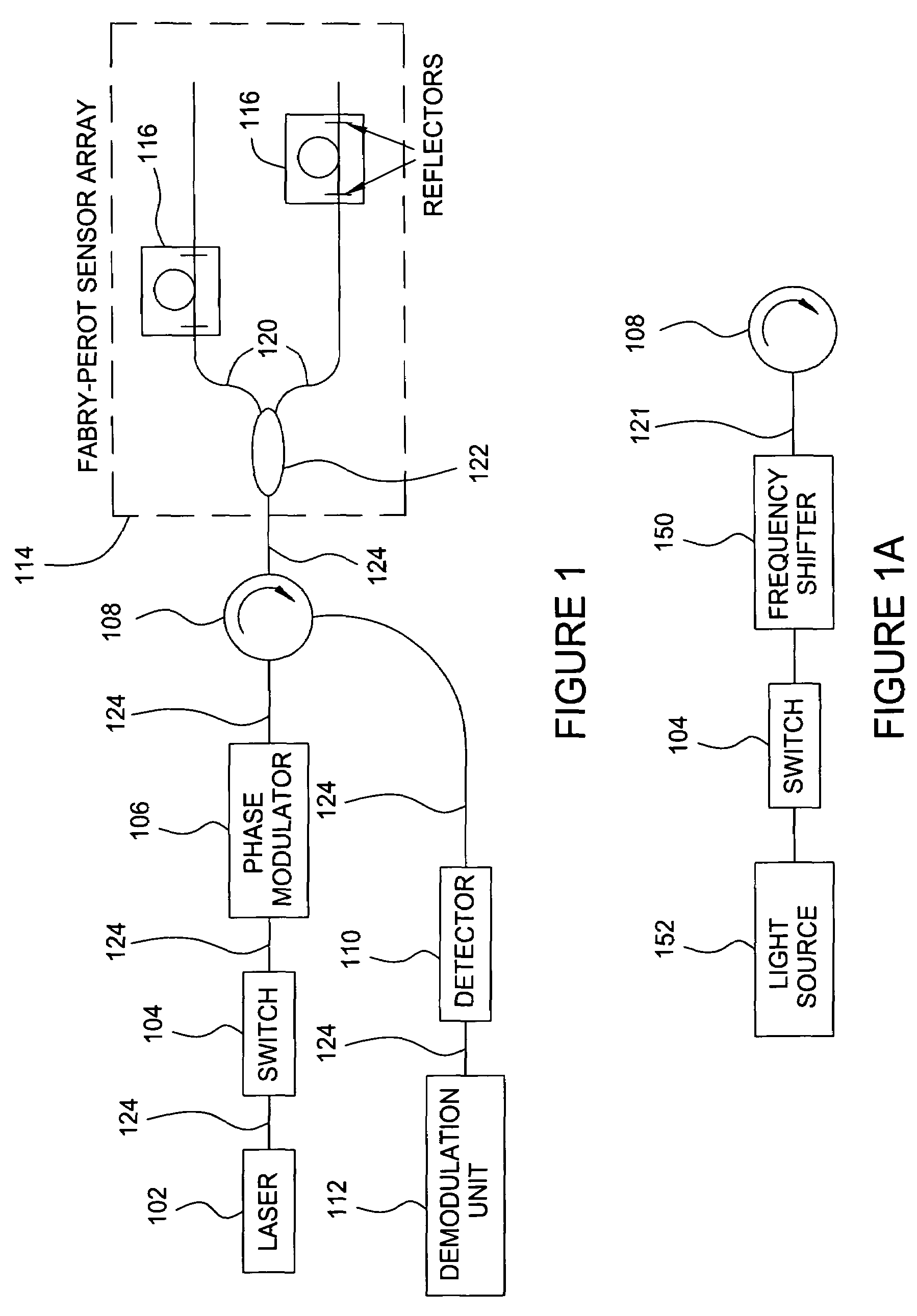
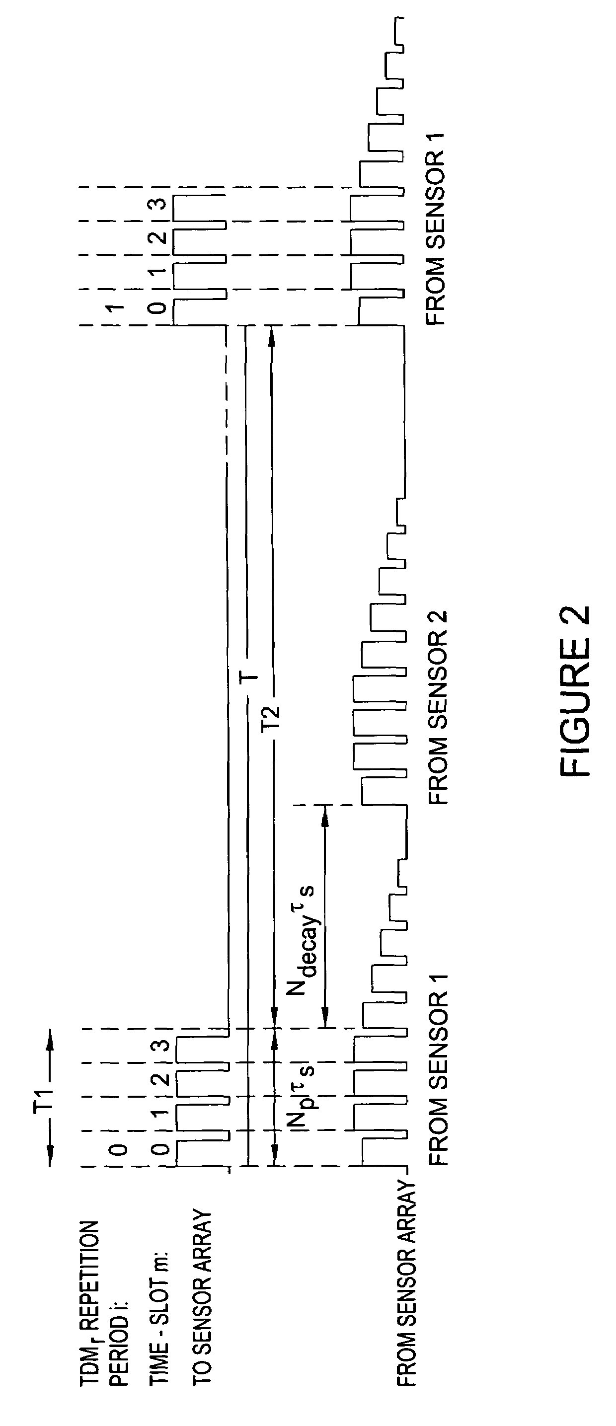
"The present invention provides methods for improving the interrogation of time-multiplexed interferometric sensors using multiple interrogation pulses. The methods increase the allowable interrogation pulse duty-cycle and improve the signal-to-noise ratio. The invention involves generating a sequence of multiple interrogation pulses in each TDM repetition period, where the optical frequencies produced in different transmission time-slots are different. The interference pulses from each sensor interferometer will interfere, forming interference pulse number m out of a sequence of Np−1 interference pulses that arrives at the receiver within each TDM repetition period. The detected interference pulses from receiver time slot m in sequence of TDM periods will contain a sub-carrier signal component with frequency Δν. The sensor phase is calculated by combining phase information from sub-carrier signals extracted from several or all of the receiver time slots."

Problems solved by technology

The time delay difference between the two paths of a sensor is called the imbalance of that sensor.
The phase generated carrier technique is based on a harmonic bias modulation of the sensor phase, for instance by modulation of the source phase, resulting in a detected interference signal that has signal components at harmonics of the source modulation frequency.
Thus, most of the interrogation pulse duty-cycle is wasted by having to wait for the multiple reflections to fade.
Other types of interferometric sensors have similar problems in that overlapping pulse reflections have to be prevented.

Method used


Image

  • Multi-pulse heterodyne sub-carrier interrogation of interferometric sensors
  • Multi-pulse heterodyne sub-carrier interrogation of interferometric sensors
  • Multi-pulse heterodyne sub-carrier interrogation of interferometric sensors

Examples


Embodiment Construction

[0020]The present invention provides for interrogating time-multiplexed interferometric sensors using multiple interrogation pulses in a manner that avoids the necessity of allowing all multiple reflections from a Fabry-Perrot interferometer to fade out at the receiver before reflections of a new interrogation pulse or signal sequence arrives at the receiver. Because the principles of the present invention enable interrogating time-multiplexed interferometric sensors without requiring time delays to fade out reflections of the interrogation pulses from prior interrogations, the inventive principles can enhance the signal-to-noise ratio of sensor measurements. The principles of the present invention represent an enhancement of the two pulse heterodyne sub-carrier technique in a manner such that the phase difference between any two subsequent pulses within one repetition period always changes by the same amount from one repetition period to the next.

[0021]FIG. 1 illustrates a fiber-op...


PUM

PropertyMeasurementUnit
time-aaaaaaaaaa
optical frequenciesaaaaaaaaaa
optical frequencyaaaaaaaaaa

Abstract

A method for interrogating time-multiplexed interferometric sensors using multiple interrogation pulses so as to increases the allowable interrogation pulse duty-cycle and improve the signal-to-noise ratio. In each TDM repetition period a sequence of multiple interrogation pulses are generated. The pulses in the sequence are separated by a time that is equal to the sensor imbalance. The phase from pulse to pulse in each TDM time-slot is modulated at a different, linear rate such that the pulse in time-slot m will have an optical frequency that is shifted by mΔν, where Δν is the sub-carrier frequency. Because multiple reflections do not need to fade out the inventive method can enhance the signal-to-noise ratio of interferometric sensors such as inline Fabry-Perot sensors.

Description

BACKGROUND OF THE INVENTION[0001]1. Field of the Invention[0002]The present invention generally relates to time division multiplexed interferometric sensors. More specifically, the present invention relates to interrogating interferometric sensors in a manner that increases the allowable interrogation pulse duty-cycle and that improves signal-to-noise ratios.[0003]2. Description of the Related Art[0004]Time division multiplexing (TDM) of interferometric sensors is performed using pulsed light sources to produce pulse reflections from the sensors such that the reflections are distributed in time because of the different time delays associated with each sensor. The requirement that the reflections from the different sensors be separated in the time domain results in the need to use pulse duty cycles and pulse repetition rates that take into account the number of sensors being sensed and their separations.[0005]An interferometric sensor may be described as being comprised of two paths ...

Claims


Application Information

Patent Timeline
Patent Type & Authority Patents(United States)
IPC IPC(8): G01B9/02G01D5/26G01D5/353G02FG02F1/21H04B10/04H04J14/08
CPCG01D5/35383
Inventor WAAGAARD, OLE HENRIKRONNEKLEIV, ERLEND
Owner OPTOPLAN
Learn More