3D fast fault restoration

a fault restoration and 3d seismic technology, applied in the field of seismic interpretation, can solve the problems of lack of mechanics-based foundation, often broken seismic features in a 3d seismic dataset, and difficulty in correct correlation by seismic interpreters, and achieve the effect of high accuracy and great efficiency

Active Publication Date: 2009-01-20
LANDMARK GRAPHICS CORP
View PDF3 Cites 66 Cited by
  • Summary
  • Abstract
  • Description
  • Claims
  • Application Information

AI Technical Summary

Benefits of technology

[0016]One embodiment uses an elasticity model as the unifying approach for both 2-D and 3-D coordinates, and in result, delivers a consistent solution for all cases. The physical model disperses the slip vector from the fault surface to other parts of the region in consistency with an elastic deformation model. This provides for the handling of faults in a complex geometry, and may easily be extended from 2-D to 3-D cases. One embodiment also comprises a special technique that solves the finite element equation and a boundary element equation in a very efficient manner such that the technique can be used in an iterative and interactive way. Thanks to the special numerical technique, the method may provide the computational performance necessary for interactive graphical operations. This enhanced computational performance allows users of the method to quickly and graphically experiment with many seismic scenarios while obtaining geologically consistent interpretations and images. Examples may be used to validate the method, and the underlying theory dictates minimal distortion of markers, such as seismic reflectors, within the restored volume sections.
[0018]Once a formulation of the 3D restoration problem has been created, the problem may be solved to yield the 3D restoration solution. For solving the problem numerically, the method may decompose the boundaries of the faulting volumes into small elements of a simple geometry. The decomposition of the surface into small elements is performed in one embodiment of the present invention using elements corresponding to a general triangle, each of which comprises 3 vertices and a surface area.
[0021]The method thus may provide a numerical result that represents the un-faulted, i.e., 3D restored, state of the formation. Seismic events may be so restored to a pre-faulting state, and interpretation and stratigraphic analysis can then be carried out with great efficiency and high accuracy. The utility of the embodiments described herein may further extend to providing 3D restoration results in a form that may be readily used for display, storage, reporting, testing, assessments and further numerical analyses; for example, the results may be extremely useful for further simulation, modeling, or validation involving theoretic or experimental seismic data.

Problems solved by technology

Consequently, the seismic features in a 3D seismic dataset are often broken at faults.
Seismic interpreters often struggle to correctly correlate features in a formation resulting from seismic events across a fault.
The results of that approach, although they may appear visually reasonable in 2-D views, lack a mechanics-based foundation.
Additionally, the dispersion formulation may be complicated in practice for 3-D cases.
Therefore, fault growth models are of limited significance in 3D fault restoration—even when the goal of the restoration is to provide a mechanically sound method.
For 3D fault reversal problems, existing methods (such as the displacement extrapolation with scan lines) are overly simplified and cannot handle the infinite combinations of the azimuth and dip of the fault surface.
Typical faults are vastly more complex than as shown in FIG. 1; thus a 2D restoration method is very limited in scope, and ergo usefulness.

Method used


Image

  • 3D fast fault restoration
  • 3D fast fault restoration
  • 3D fast fault restoration

Examples


Embodiment Construction

[0033]In the following description, numerous specific details are set forth such as specific reference algorithms to provide a thorough understanding of embodiments of the present invention. However, it will be obvious to those skilled in the art that embodiments of the present invention may be practiced without such specific details. In other instances, well-known mathematical method steps or components have been omitted or shown in block diagram form in order not to obscure the present description in unnecessary detail. For the most part, details concerning specific timing considerations and the like have been omitted inasmuch as such details are not necessary to obtain a complete understanding of the methods described herein and are within the skills of persons of ordinary skill in the relevant art.

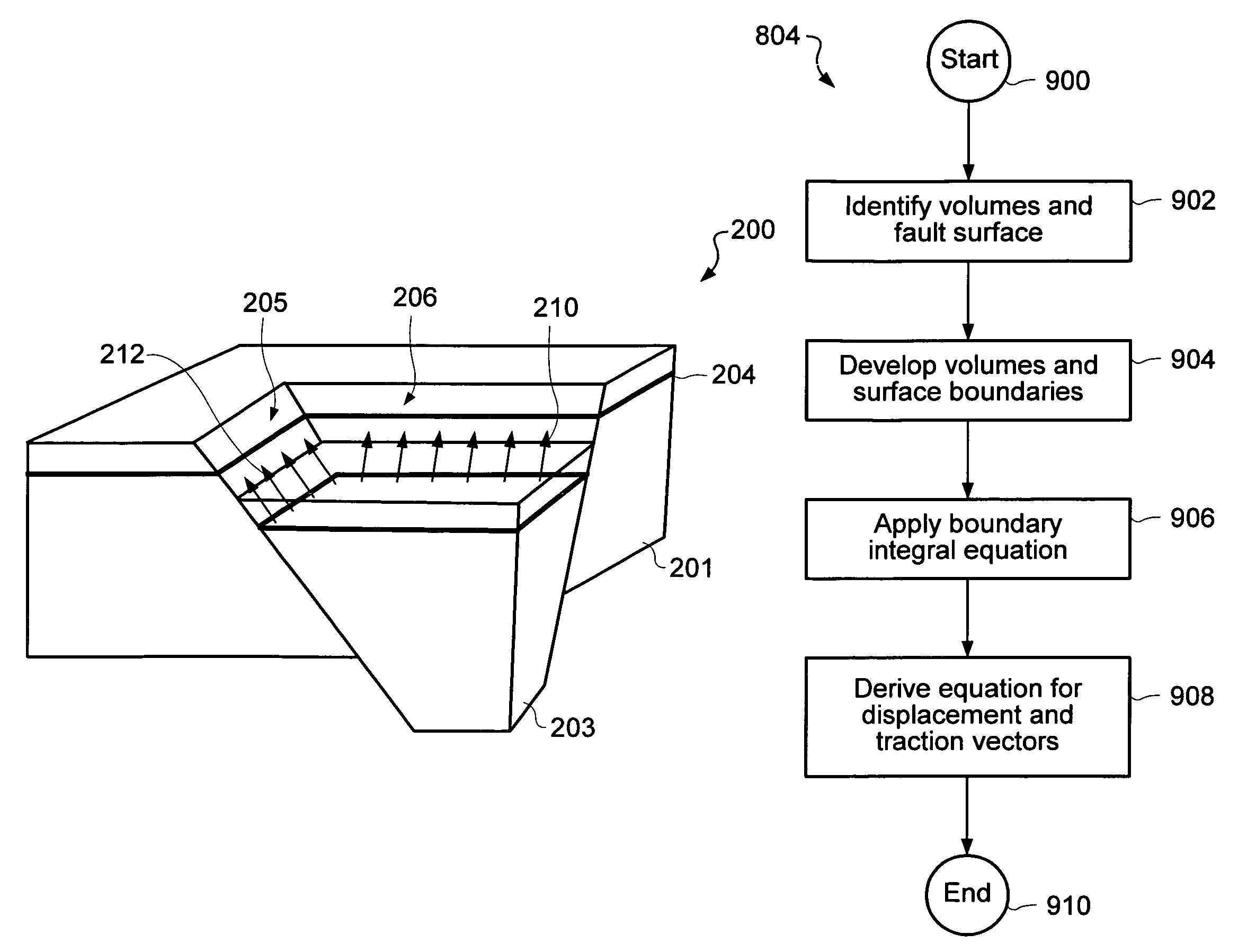
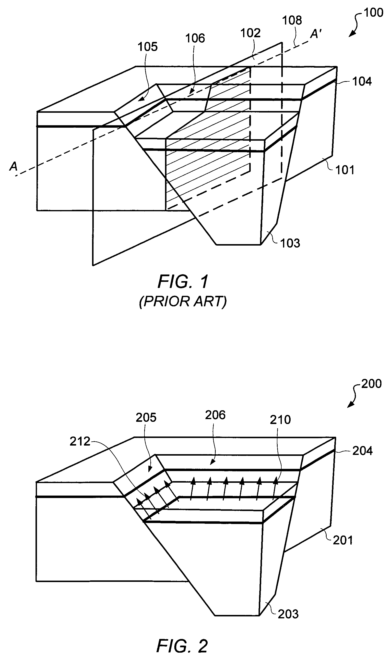
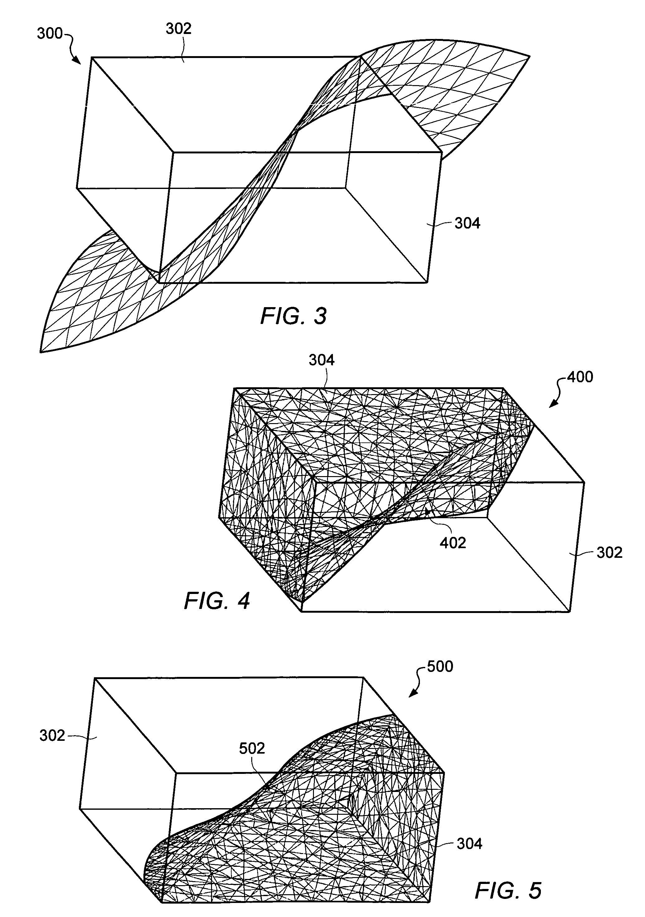
[0034]One embodiment of the invention formulates the deformation problem to remove subsurface faulting fault with an elastic model and solves the deformation problem by a numerical met...


PUM


Abstract

Solutions to the problem of reversing seismic fault movements are formulated using a model based on elasticity theory, and using finite element and boundary element methods for generating a solution. The solution involves defining slip vectors from known formations in the fault and applying a space constraint restriction to traction values on the fault surface. The method may be applied in either 2D or 3D applications. The method is computationally fast enough to allow interactive fault reversal, and permits experimentation with various unfaulting scenarios so that a geologically acceptable solution is provided.

Description

PRIORITY CLAIM[0001]This application claims the benefit of priority under 35 U.S.C. §119(e) to U.S. Provisional Application No. 60 / 673,263, filed on Apr. 20, 2005, entitled “Fast Elasticity Modeling and Numerical Solutions of Seismic Un-Faulting”, invented by Kaihong Wei.BACKGROUND OF THE INVENTION[0002]1. Field of the Invention[0003]This invention relates generally to the field of seismic interpretation, and more particularly, to modeling the restoration of a seismic fault.[0004]2. Description of the Related Art[0005]Faults in the crust of the earth cut through the sedimentary strata and offset them. Consequently, the seismic features in a 3D seismic dataset are often broken at faults. Seismic interpreters often struggle to correctly correlate features in a formation resulting from seismic events across a fault. A seismic fault can distort the depositional characteristics of a formation and even obscure hydrocarbon reservoirs that may be present and recoverable. Therefore, a way to...

Claims


Application Information

Patent Timeline
Patent Type & Authority Patents(United States)
IPC IPC(8): G01V1/30
CPCG01V1/282G01V2210/66G01V2210/661
Inventor WEI, KAIHONG
Owner LANDMARK GRAPHICS CORP
Why Eureka
Try Eureka