Multiple sensor flow meter

a flow meter and sensor technology, applied in the direction of liquid/fluent solid measurement, volume/mass flow by differential pressure, instruments, etc., can solve the problem of unacceptably high measurement error, and achieve the effect of moderate to high measurement accuracy

Inactive Publication Date: 2009-01-20
ONICON INC
View PDF13 Cites 18 Cited by
  • Summary
  • Abstract
  • Description
  • Claims
  • Application Information

AI Technical Summary

Benefits of technology

[0008]As an additional example, consider a quad-sensor ultrasonic flow meter. If one of the sensors becomes defective, as indicated by its inability to provide flow rate data approximating its backup data, its backup data can then contribute to the meter output along with that of the other three sensors which are considered to be operating properly. Should one of the remaining operational sensors similarly become defective, its backup data is also substituted for its current data. Should one of the two remaining sensors catastrophically fail—i.e., so that it is certain which one has failed, its backup data is also used to substitute for its current data. The meter precision would then be dependent on the data contributions of the sole remaining operational sensor and the backup data from the three defective sensors and will be degraded only a relatively small amount in a typical application. The ability of the meter to still provide the needed metering precision after one or more of its sensors have become defective is a major advantage and allows a meter operator to service the flow meter when convenient, rather than immediately.
[0009]The present invention is particularly effective in an application where meter installation is less than ideal, meter servicing is difficult, and a moderate to high degree of measurement precision is required. An example of such an application is the flow rate measurement in large hydronic heating and cooling loops in large buildings. These loops often have limited straight runs in convenient locations and are difficult to drain so that a flow meter can be replaced or serviced.

Problems solved by technology

In addition, using multiple flow rate sensors provides a degree of redundancy so that if one local sensor fails, the remaining flow rate sensor or sensors may still be able to provide a usable flow rate indication until repairs are made.
In cases such as this, dropping the output from a failed sensor and using the outputs from the remaining ones can lead to an unacceptably high error in the measurement.

Method used


Image

  • Multiple sensor flow meter
  • Multiple sensor flow meter
  • Multiple sensor flow meter

Examples


Embodiment Construction

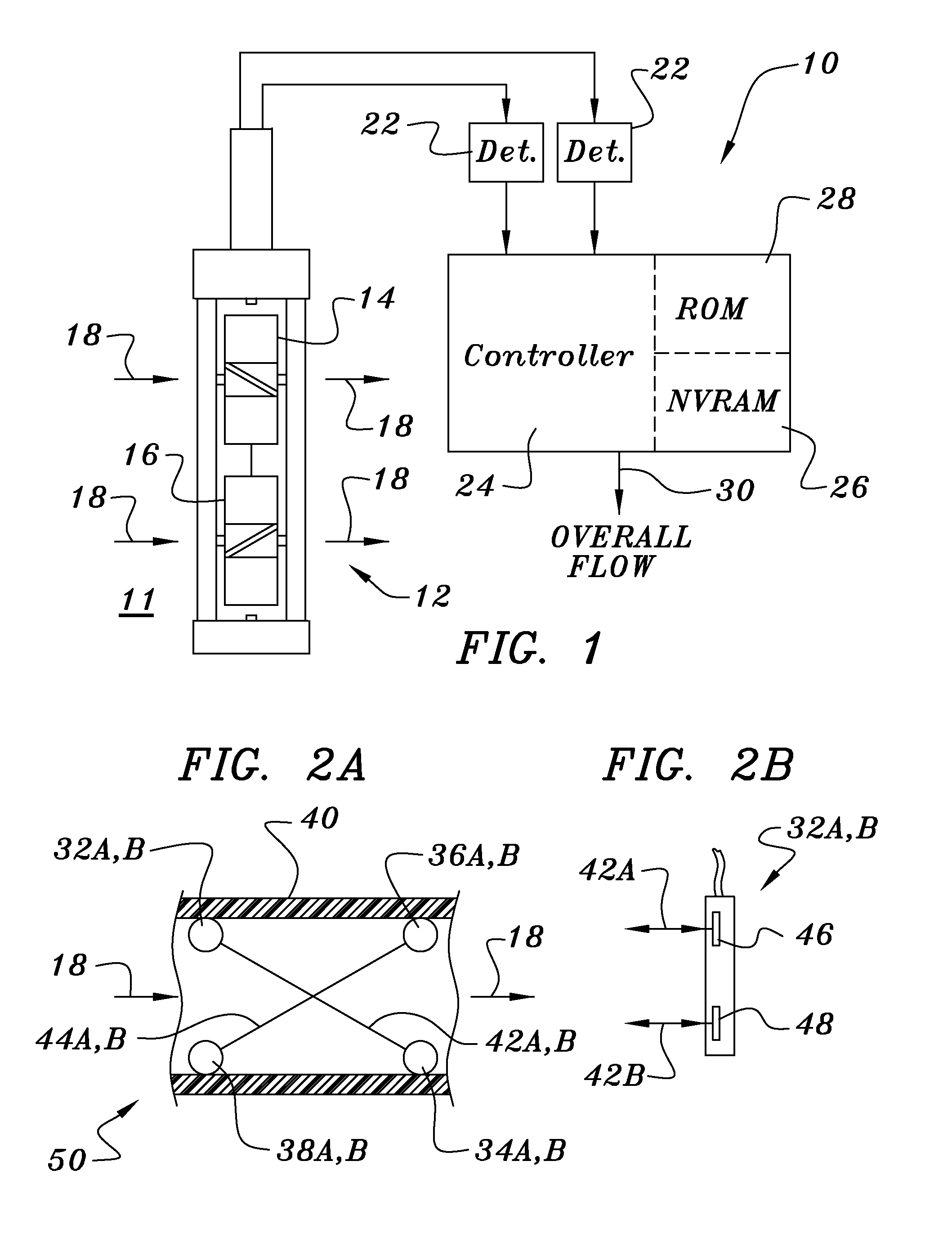
[0017]Turning now to FIG. 1, one finds a schematic block depiction of an embodiment of the flow meter of the invention 10 that employs an assembly 12 comprising two contra-rotating turbine elements 14 and 16. This arrangement allows for continued operation even if one of the two turbine elements fails or becomes temporarily clogged—e.g., by a leaf entrained in a water pipe. The arrows 18 show the direction of flow of the fluid 11 through the sensor assembly 12. In normal operation the rotational rates of the two turbines are individually detected by rotation detectors 22 and the two rotational rate signals are processed by a microcontroller 24, which provides a composite flow rate output signal 30.

[0018]In operating the apparatus of FIG. 1, the turbine elements rotate in opposite directions, as depicted by the opposite blade pitches, so that an average of their local output signals compensates for swirl in the flow stream and is usually provided as the composite flow rate output. A ...


PUM


Abstract

Combining a plurality of local flow measurements made at more than one location to generate a composite flow value can improve the accuracy of the overall measurement. The reliability and long term accuracy of a multi-sensor flow measurement are improved by a two-step process. During an initial learning period, when all of the local sensors are providing accurate local measurements, a calibration table is built up that associates each calculated composite flow value with the set of local flow signal values from which it was calculated. In a subsequent operational period each time the composite flow rate is to be determined the flow meter apparatus first checks to see if all the local sensors are working properly and, if one of them is not working properly, its output is replaced with the corresponding value from the calibration table.

Description

BACKGROUND OF THE INVENTION[0001]The present invention relates to apparatus and methods for measuring an overall flow rate of a fluid with particular emphasis on methods made by combining a plurality of local measurements.[0002]Combining a plurality of local flow measurements made at more than one location in the cross section of a flow profile to generate a composite flow value representative of the overall flow rate can improve the accuracy of the overall measurement. In addition, using multiple flow rate sensors provides a degree of redundancy so that if one local sensor fails, the remaining flow rate sensor or sensors may still be able to provide a usable flow rate indication until repairs are made.[0003]Generating a composite flow output from a plurality of local sensors can be important when measuring a highly inhomogeneous flow. Such a situation can arise, for example, where the flow measurement must be made very close to a piping structure, such as a ninety degree elbow, tha...

Claims


Application Information

Patent Timeline
Patent Type & Authority Patents(United States)
IPC IPC(8): G01F1/00G01F1/50G01F25/00G01F7/00G06F19/00
CPCG01F1/00G01F1/125G01F1/667G01F1/668G01F25/0007G01F25/10
Inventor FELLER, MURRAY F
Owner ONICON INC
Why Eureka
Try Eureka