Charge pump apparatus

a pump and pump body technology, applied in pulse generators, pulse techniques, instruments, etc., can solve the problems of reducing operating voltage, power consumption, body effect, etc., and achieve the effects of low power consumption, high efficiency, and small area

Active Publication Date: 2019-05-14
EMEMORY TECH INC
View PDF19 Cites 0 Cited by
  • Summary
  • Abstract
  • Description
  • Claims
  • Application Information

AI Technical Summary

Benefits of technology

[0005]The present invention is directed to a charge pump apparatus with the characteristics of high efficiency, small area and low power consumption, being without the problem of body effect, and the voltage needed can be generated accurately.
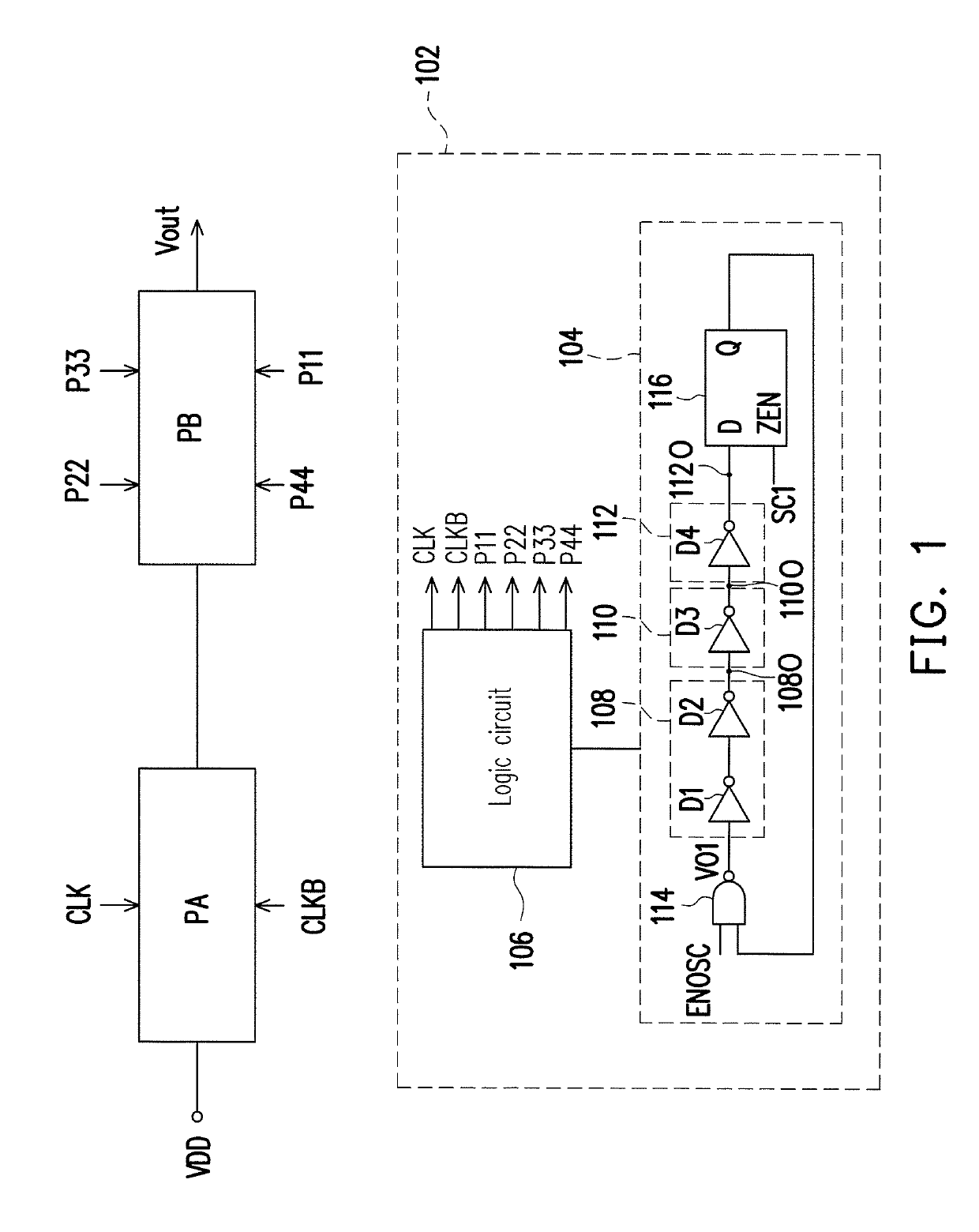
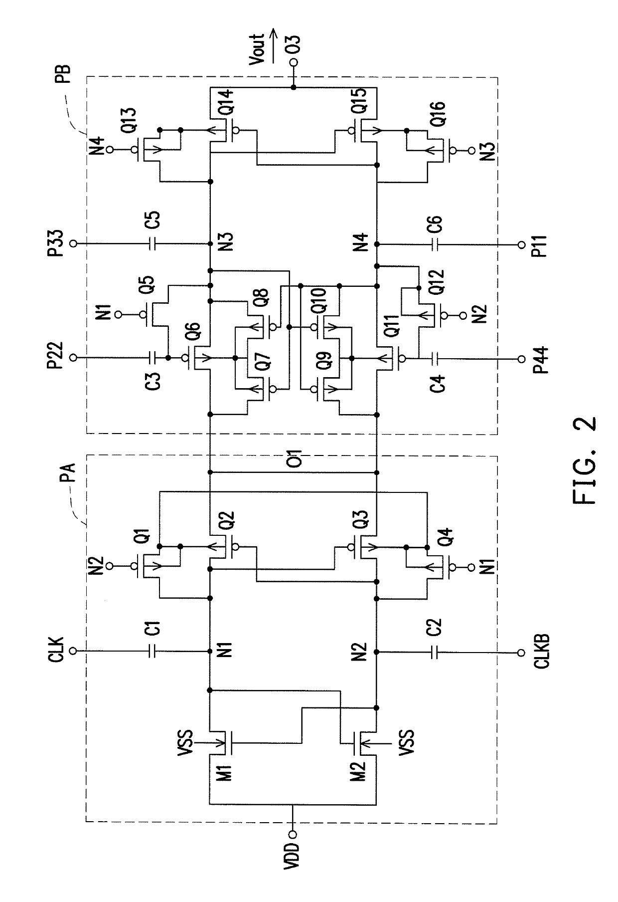
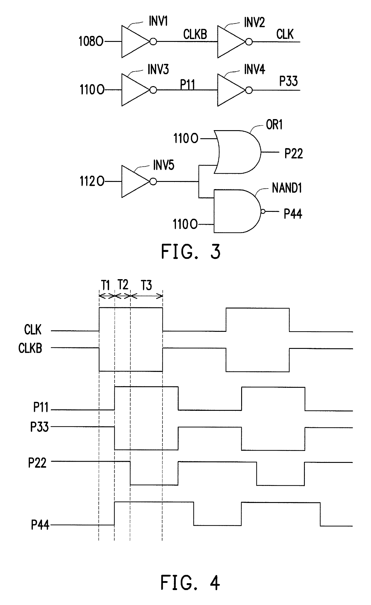
[0025]Based on the above, the charge pump apparatus of the embodiments of the present invention generates a two-phase clock signal and a four-phase clock signal for respectively driving a two-phase charge pump circuit and a four-phase charge pump circuit according to delay signals of coupling nodes between delay circuits of a ring oscillator circuit, therefore the additional delay circuits for generating the clock signals for driving the four-phase charge pump circuits is unnecessary, and the advantages of the two-phase charge pump circuit and the four-phase charge pump circuit are combined by serial connecting the two-phase charge pump circuit and the four-phase charge pump circuit, so the charge pump apparatus has the characteristics of high efficiency, small area and low power consumption, and being without the problem of body effect, therefore the voltage needed can be generated accurately.

Problems solved by technology

It has been prone to reduce the operating voltage of the semiconductor memory apparatus to reduce the electrical power consumption in these years.
However, part of circuit of the semiconductor memory such as word line diver or output driver still need to be operated under a relatively high voltage.
The two-phase charge pump circuit has higher efficiency, occupies smaller area and has lower power consumption; however, a problem of body effect exists in the circuit if deep Nwell not provided in process flow.
On the other hand, although the problem of body effect does not exist in the four-phase charge pump circuit, the efficiency thereof is lower.

Method used


Image

  • Charge pump apparatus
  • Charge pump apparatus
  • Charge pump apparatus

Examples


Embodiment Construction

[0039]The term “couple” used in the present application (including the claims) can be referred as any direct or indirect ways of connection. For example, “first apparatus is coupled to second apparatus” can be explained as “first apparatus is directly coupled to second apparatus”, or “first apparatus is indirectly coupled to second apparatus through other apparatus or connecting means”. In addition, the elements / apparatus / steps with the same reference number are indicating the same or like parts in appropriate places of the drawings and the descriptions. The elements / apparatus / steps with the same reference numbers in different embodiments may be referred to each other.

[0040]Multiple embodiments are provided below to detail describe the disclosure, but the disclosure is not limited to the embodiments provided, and the provided embodiments may be combined in an appropriate way. In the following embodiments, the same or like numbers stand for the same or like elements or signals.

[0041]...


PUM


Abstract

A charge pump apparatus is provided. A two-phase clock signal and a four-phase clock signal for respectively driving a two-phase charge pump circuit and a four-phase charge pump circuit are generated according to delay signals of coupling nodes between delay circuits of a ring oscillator circuit.

Description

CROSS-REFERENCE TO RELATED APPLICATION[0001]This application claims the priority benefits of U.S. provisional application Ser. No. 62 / 362,068, filed on Jul. 14, 2016. The entirety of the above-mentioned patent application is hereby incorporated by reference herein and made a part of this specification.BACKGROUNDTechnical Field[0002]The present invention relates to a charge pump apparatus, and more particularly to a charge pump apparatus including a two-phase charge pump circuit and a four-phase charge pump circuit.Description of Related Art[0003]It has been prone to reduce the operating voltage of the semiconductor memory apparatus to reduce the electrical power consumption in these years. However, part of circuit of the semiconductor memory such as word line diver or output driver still need to be operated under a relatively high voltage. Accordingly, the charge pump circuit plays an important role in the semiconductor memory apparatus.[0004]Generally speaking, the types of the cha...

Claims


Application Information

Patent Timeline
Patent Type & Authority Patents(United States)
IPC IPC(8): H03H11/26H03K19/20G11C16/12H02M3/07H03K3/03H03K17/28G11C5/14H02M1/00G11C16/04
CPCG11C5/145G11C16/12H02M3/073H03K17/28H03K19/20H03K3/0315H02M2001/007G11C16/0433H02M1/007
Inventor SHAO, CHI-YI
Owner EMEMORY TECH INC
Why Eureka
Try Eureka