Tank system with fuel level gauge

a fuel level gauge and tank system technology, applied in liquid handling, instruments, packaged goods types, etc., can solve the problems of inability to reliably control the pressure refueling device, inability to reliably evaluate the management system, and severe malfunctions, and achieve high reliability and fault tolerance, negligible effect of fuel weight in the tank

Inactive Publication Date: 2009-01-27
AIRBUS HELICOPTERS DEUT GMBH
View PDF13 Cites 7 Cited by
  • Summary
  • Abstract
  • Description
  • Claims
  • Application Information

AI Technical Summary

Benefits of technology

[0018]The use of the fuel-permeable, thin-walled enveloping element with its special arrangement however, makes it possible to effectively avoid the disadvantageous effects these detrimental effects have on the measuring procedure. After all, before the fuel can reach the measuring pipe, it first has to flow through the large-surface enveloping element. This largely suppresses bubble and foam formation in the fuel. The fuel permeability and the length of the penetration segment that is defined especially by the thickness of the enveloping element should be selected here in such a way that the entry of the fuel into the antechamber and the flow of the fuel from there into the measuring pipe are not excessively delayed or are not delayed at all since this, in turn, could cause a detrimental measuring delay or a measuring error. Moreover, the enveloping element acts as a kind of damping element for the sloshing fuel that is highly turbulent and that is flowing into the tank at a high pressure, so that the fuel is already stabilized when it flows into the antechamber. In this manner, strong fluctuations of the fuel level, which is continually changing during the refueling operation, are avoided in the antechamber and in the downstream measuring pipe. The antechamber itself also acts as a kind of damping chamber from which the further stabilized fuel then flows uniformly via the fuel inlet opening into the measuring pipe and gradually fills it steadily and without strong turbulences or level fluctuations, as the refueling operation progresses.
[0019]As a result, the measurement-sensitive sensor area of the fuel level sensor is always operating in an optimal measuring environment. In this manner, during the entire (pressure) refueling operation, the fuel level in a tank as the refueling operation progresses and the resultant fuel volume and the fuel weight in the tank can all be reliably determined. The fuel level gauge according to the invention can fundamentally be configured without mechanically moving parts, which ensures a high reliability and fault tolerance. Moreover, conventional fuel level gauges can easily be retrofitted so as to have the configuration according to the invention. The additional weight created by the enveloping element and its fastening elements is negligibly small, which is particularly advantageous for light-weight aviation applications. In summary, the fuel level gauge according to the invention is a technically effective as well as very economical and cost-effective solution.
[0020]According to a second aspect, the present invention provides a fuel level gauge including:
[0021]a measuring pipe configured as a riser pipe that has a fuel inlet opening at one end area and that defines a measuring distance;
[0022]a fuel level sensor that is associated with the measuring pipe, that is arranged in the vicinity of the fuel inlet opening and that is provided with a measurement-sensitive sensor area, for purposes of measuring the fuel filling height in the measuring pipe;
[0023]a (rigid or flexible) housing that is fitted with a fuel inlet channel and that surrounds a first area of the measuring pipe so as to seal it and that encloses a second area of the measuring pipe at a predefined distance over a large surface, said second area encompassing at least the fuel inlet opening and the measurement-sensitive area of the fuel level sensor, and forming a large-volume antechamber upstream from the fuel inlet opening in this second area between the inside of said housing and the measuring pipe, and

Problems solved by technology

It has been found that, with a number of conventional fuel level gauges intended for aircraft, quite severe malfunctions occur, especially during pressure refueling, which manifest themselves in impermissible measured signals and in a measured curve that is useless when considered over the course of the refueling time.
The lack of reliability of the measured signal or the uselessness of the measured curve means that the fuel management system cannot reliably evaluate the measured data of the fuel level gauge during the refueling, the pressure refueling device cannot be reliably controlled and the above-mentioned mission-relevant flight-mechanical parameters cannot be precisely determined.

Method used


Image

  • Tank system with fuel level gauge
  • Tank system with fuel level gauge
  • Tank system with fuel level gauge

Examples


first embodiment

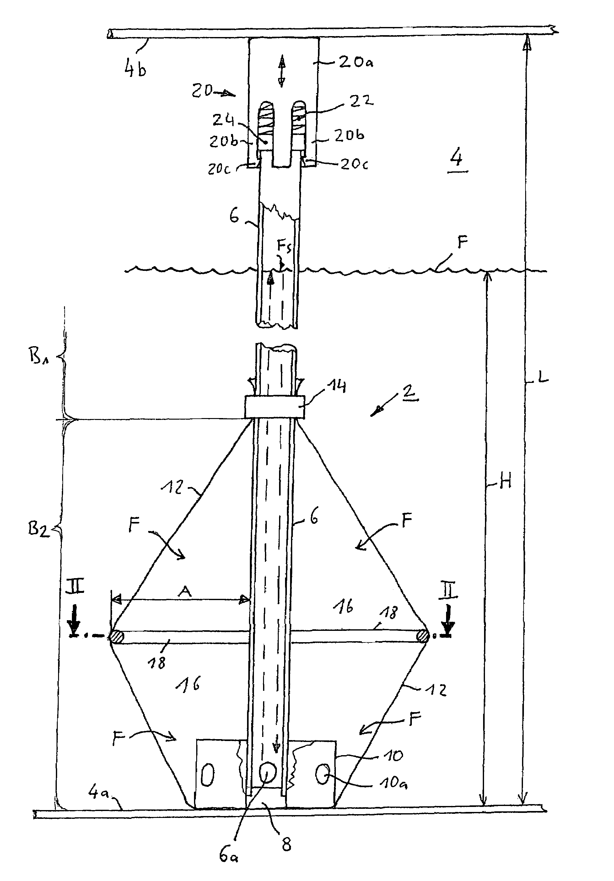
[0038]FIG. 1 shows a schematic, partially cutaway side view through a fuel level gauge 2 according to the invention mounted in a fuel tank 4 in a For the sake of clarity, only the bottom of the tank 4a and the top of the tank 4b of the fuel tank 4 are indicated The fuel level gauge 2 comprises a measuring pipe 6 configured as a riser pipe that has a fuel inlet opening 6a at one end area through which the fuel F can reach the inside of the measuring pipe 6. The measuring pipe 6 defines a measuring distance. A fuel level sensor 8 for measuring a fuel filling height H in the measuring pipe 6 is arranged at the lower end of the measuring pipe 6. This sensor 8 is preferably arranged in the vicinity of the fuel inlet opening 6a and has a measurement-sensitive sensor area. The sensor 8 in this example is an ultrasound fuel level sensor that, as the refueling operation progresses, measures the particular filling height H of the fuel F inside the measuring pipe 6 by measuring the propagatio...

second embodiment

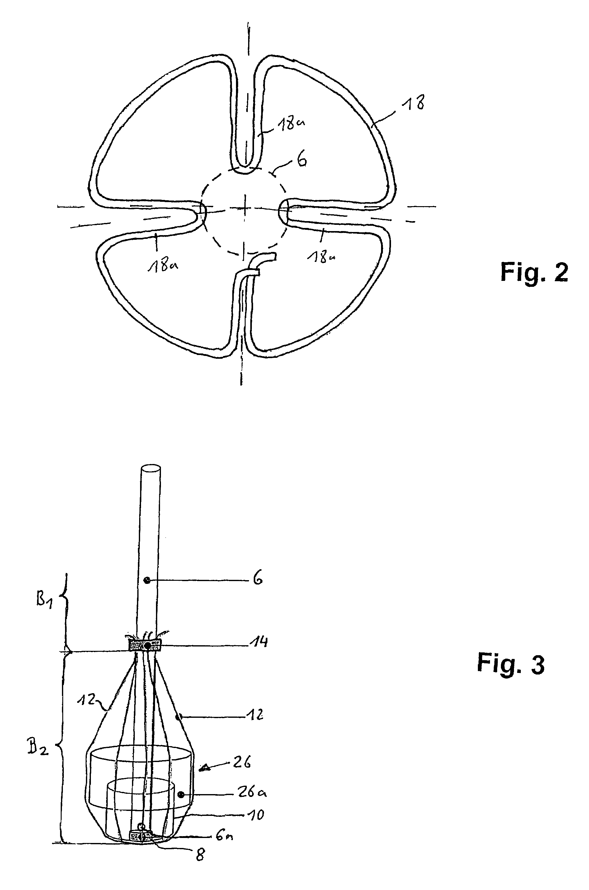
[0049]FIG. 3 shows a schematic three-dimensional, grid-like representation of a fuel level gauge 2 according to the invention in a This variant largely matches the one in FIGS. 1 and 2. Instead of the spacer 18 in the form of a bent wire ring, however, a different construction is used. As indicated in FIG. 3, a fuel density sensor 26 is provided in the second area B2 of the measuring pipe 6 and this fuel density sensor 26 has a virtually cylindrical sensor housing 26a that extends concentrically around the measuring pipe 6 and part of the labyrinth 10. In this example, the diameter of the sensor housing 26a is about 3 to 5 times the outer diameter of the measuring pipe 6. The sensor housing 26a serves as a spacer for the enveloping element 12 and thus fulfills an advantageous dual function. In FIG. 3, the enveloping element 12 is only indicated by a few lines in order to indicate the envelope shape of the enveloping element 12. The fuel density sensor 26 is a capacitive sensor that...

third embodiment

[0050]FIG. 4 shows a schematic longitudinal sectional view through a fuel level gauge 2 according to the invention in a third embodiment This variant uses various components that are already known from the embodiments of FIGS. 1 to 3, which is indicated by the use of the same reference numerals. However, the embodiment according to FIG. 4 differs from that of FIGS. 1 to 3 especially in terms of the arrangement and functionality of the fuel-permeable, thin-walled enveloping element 12.

[0051]As can be seen in FIG. 4, a housing 28 is installed on the measuring pipe 6, whereby said housing 28 surrounds the first area B1 of the measuring pipe 6 so as to seal it and encloses the second area B2 at a predefined distance A over a large surface, said second area B2 comprising at least the fuel inlet opening 6a and the measurement-sensitive area of the fuel level sensor 8. In this second area B2, the housing 28 forms a large-volume antechamber 16 between the inside of said housing 28 and the o...


PUM


Abstract

A fuel level gauge includes a measuring pipe configured as a riser pipe that has a fuel inlet opening at one end region defines a measuring distance. The fuel level gauge also includes a fuel level sensor associated with the measuring pipe and disposed the vicinity of the fuel inlet opening and having a measurement-sensitive sensor area for purposes of measuring the fuel filling height in the measuring pipe. A fuel-permeable, thin-walled enveloping element surrounding the measuring pipe tightly so as to seal it in a first area of the measuring pipe and enclosing a second area of the measuring pipe at a predefined distance over a large surface. The second area encompasses at least the fuel inlet opening and the measurement-sensitive area of the fuel level sensor, and forms a large-volume antechamber upstream from the fuel inlet opening in the second area between an inside of the enveloping element and an outside of the measuring pipe.

Description

[0001]Priority is claimed to German Patent Application No. DE 10 2005 011 049.5, filed on Mar. 8, 2005, the entire disclosure of which is incorporated by reference herein.[0002]The present invention relates to a fuel level gauge, to a tank system having such a fuel level gauge as well as to an aircraft, especially to a rotary-wing aircraft such as, for example, a helicopter, having such a tank system.BACKGROUND[0003]Fuel level gauges are used to determine the filling height in a fuel tank and from that, in turn, the filling volume of the tank. Such devices are known in a variety of configurations. Fuel level gauges, for instance, for vehicles, are relatively simple in design and have fuel level sensors, for example, in the form of simple float constructions or the like. However, fuel level gauges for applications in aviation are quite complex in design.[0004]This is due to the fact that, among other things, it has to be possible to refuel aircraft—as a function of the type of aircra...

Claims


Application Information

Patent Timeline
Patent Type & Authority Patents(United States)
IPC IPC(8): G01F23/296
CPCG01F23/2962
Inventor SCHILLINGER, ALEXANDERHEINDEL, GUENTHER
Owner AIRBUS HELICOPTERS DEUT GMBH
Why Eureka
Try Eureka