
Apparatus for improving the cold starting capability of an electrochemical fuel cell

a fuel cell and apparatus technology, applied in the direction of cell components, electrochemical generators, cell component details, etc., can solve the problems of damage to the structure within the stack, expansion of water remaining in the stack passage, etc., to improve the cold start capability and freeze tolerance of the fuel cell stack

Inactive Publication Date: 2009-01-27
CELLCENTRIC GMBH & CO KG
View PDF51 Cites 5 Cited by
  • Summary
  • Abstract
  • Description
  • Claims
  • Application Information

AI Technical Summary

Benefits of technology

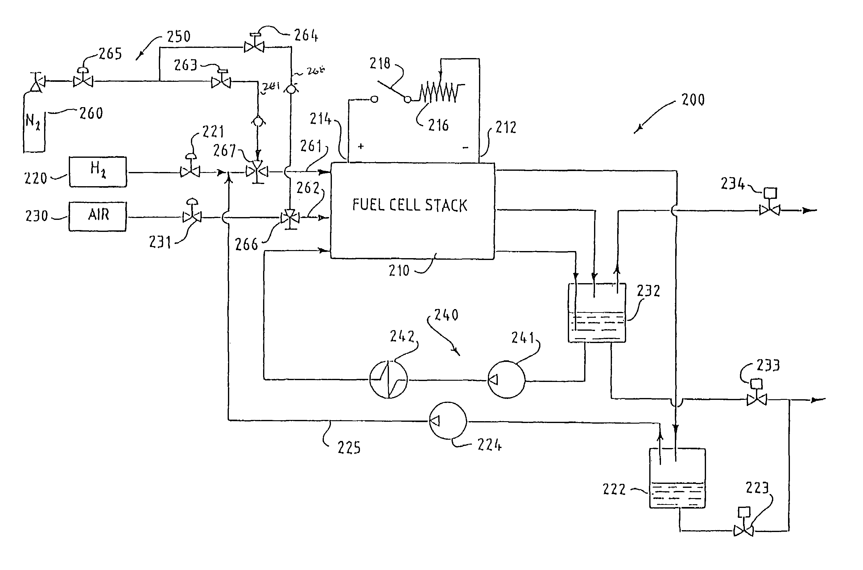
[0012]According to one aspect of the invention, an electric power generation system is provided that includes a fuel cell stack connectable to an external electrical circuit; when so connected, the stack may supply electric current to the external circuit. The stack comprises at least one solid polymer fuel cell and fluid stream passages for directing fluid streams through at least one of the fuel cells. The system also includes a purge system that has a purge conduit having an inlet end connectable to a purge fluid supply, and an outlet end connectable to at least one of the fluid stream passages. The purge system also has a purge flow control device that controls the flow of a pressurized purge fluid through the purge conduit such that water can be purged from at least one of the fluid stream passages after a supply of electric current from the stack to the external circuit has been interrupted. The purge system is operable to improve the cold start capability and freeze tolerance of its fuel cell stacks by reducing the amount of water remaining within the passages of the stack prior to stack freezing.
[0018]In shutdown methods involving a purge with reactant gas which is humidified during normal operation, humidification of the reactant gas may be reduced or stopped. This may be accomplished, for example, by directing the reactant to the stack in fluid isolation from the humidifier, or by reducing the water transfer rate to the supply reactant stream passing through the humidifier.
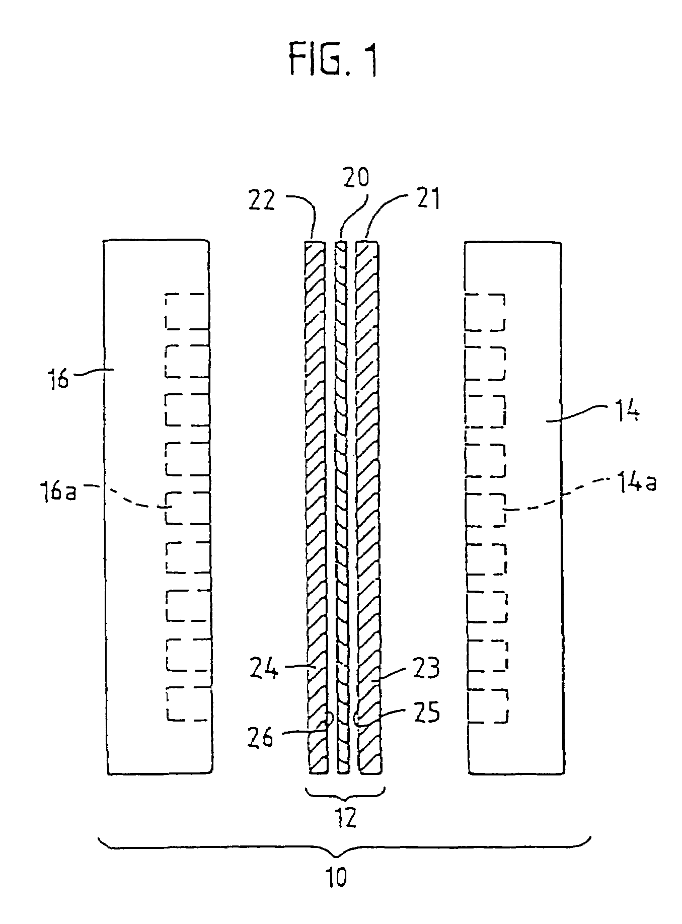
[0021]According to another aspect of the invention, there is provided a method of ceasing operation of an electric power generation system to improve the cold start capability and freeze tolerance of fuel cell stacks by reducing the amount of water remaining within the passages of the stack. The stack comprises a fuel cell stack connectable to an external electrical circuit for supplying electric current to the external circuit. The stack comprises at least one fuel cell comprising a membrane electrode assembly comprising an anode, a cathode, and an ion exchange membrane interposed between the anode and the cathode. The at least one fuel cell further comprises a fuel stream passage for directing a fuel stream to the anode and an oxidant stream passage for directing an oxidant stream to the cathode. Each of the streams is flowable to the fuel cell stack. The method comprises the sequential steps of:
[0042]This in situ “heat treatment” of a membrane electrode assembly after a cold start has been shown, in certain situations, to improve subsequent fuel cell performance of a fuel cell, relative to commencing operation without operating the cell above its normal operating temperature range. Again, this improved method is especially useful for commencing operation when at least a portion of the membrane electrode assembly has temperature below the freezing temperature of water, and particularly operation on air (rather than a substantially pure oxidant). Operationally, the in situ heat treatment method can be accomplished in a number of other ways, besides delaying flow of a coolant.

Problems solved by technology

Upon freezing, water remaining within stack passages will expand and potentially damage structures within the stack such as, for example, the membrane / electrocatalyst interface, the reactant passageways, conduits and seals, as well as the porous electrode substrate material.

Method used


Image

  • Apparatus for improving the cold starting capability of an electrochemical fuel cell
  • Apparatus for improving the cold starting capability of an electrochemical fuel cell
  • Apparatus for improving the cold starting capability of an electrochemical fuel cell

Examples


examples

Heat Treatment Methods

[0106]FIG. 14 shows a plot of stack voltage against operating time for an 8-cell Ballard Mark 513 fuel cell stack which was subjected to a series of freeze-thaw-operation cycles. Prior to freezing the fuel, oxidant and coolant passages were purged with dry gas. During the freezing cycles, the cell inlets and outlets were capped and the cell was placed in a freezer. Internal sealing pressure within the cell was maintained during freezing. The freezer temperature was approximately −20° C. The duration of the freeze in each case was greater than 12 hours. After some cycles the stack was operated normally, and after other cycles the stack operating temperature was increased to above its normal operating temperature for a period, before normal operation was resumed. The stack was operated on humidified air and hydrogen, both at 30 psig (207 kPa gauge), at stoichiometries of 2.0 and 1.5 respectively, at a current density of 700 ASF (7535 ASM) to generate the data sho...


PUM

PropertyMeasurementUnit
operating temperatureaaaaaaaaaa
freezing temperatureaaaaaaaaaa

Abstract

An electric power generation system has elements that improve the cold start capability and freeze tolerance of a constituent fuel cell stack cooperate to reduce the amount of water remaining within the passages of the stack. The system includes a purge system that is connectable to the oxidant supply, fuel supply and / or coolant passages upstream of the stack. When the stack is shut down, the stack is disconnected from an external circuit, and purge fluid is transmitted by the purge system through the stack before the stack falls below the freezing point of water. In systems where fuel and / or oxidant streams are humidified prior to entry into the stack, a humidifier bypass system may be provided in place of the purge system. The humidifier bypass system transmits reactant fluid to the stack in fluid isolation from the humidifier, so that the inlet reactant streams are unhumidified.

Description

CROSS-REFERENCE TO RELATED APPLICATION(S)[0001]This application is a continuation-in-part of U.S. patent application Ser. No. 09 / 819,875 filed Mar. 28, 2001, entitled “Apparatus for Improving the Cold Starting Capability of an Electrochemical Fuel Cell”. The '875 application is a continuation-in-part of U.S. patent application Ser. No. 09 / 406,318 filed Sep. 27, 1999, now U.S. Pat. No. 6,479,177 issued Nov. 12, 2002, entitled “Methods for Improving the Cold Starting Capability of an Electrochemical Fuel Cell”. The '318 application is a continuation-in-part of U.S. patent application Ser. No. 09 / 138,625 filed Aug. 24, 1998, now abandoned, entitled “Method and Apparatus for Commencing Operation of a Fuel Cell Electric Power Generation System Below the Freezing Temperature of Water”. The '625 application is a continuation of U.S. patent application Ser. No. 08 / 659,921 filed Jun. 7, 1996, now U.S. Pat. No. 5,798,186 issued Aug. 25, 1998, also entitled “Method and Apparatus for Commencing...

Claims


Application Information

Patent Timeline
Patent Type & Authority Patents(United States)
IPC IPC(8): H01M8/04
CPCH01M8/04007H01M8/04223H01M8/04029H01M8/04119H01M8/04156H01M2300/0082Y02E60/50H01M8/241H01M8/04303H01M8/04225H01M8/04228H01M8/2457
Inventor ROBERTS, JOY AST-PIERRE, JEANVAN DER GEEST, MARIAN EATBI, ABDERRAHMANEFLETCHER, NICHOLAS J
Owner CELLCENTRIC GMBH & CO KG
Learn More