
Electric/magnetic field sensor

a magnetic field and sensor technology, applied in the direction of resistance/reactance/impedence, electrostatic field measurement, instruments, etc., can solve the problems of limited sensitivity at low frequencies, poor response, and difficulty in fabricating a sensor having a wide pass band, so as to increase the useful wide bandwidth and expand the useful wide bandwidth

Inactive Publication Date: 2009-01-27
THE BOARD OF REGENTS NEVADA SYST OF HIGHER EDUCATION ON BEHALF OF UNLV
View PDF10 Cites 6 Cited by
  • Summary
  • Abstract
  • Description
  • Claims
  • Application Information

AI Technical Summary

Benefits of technology

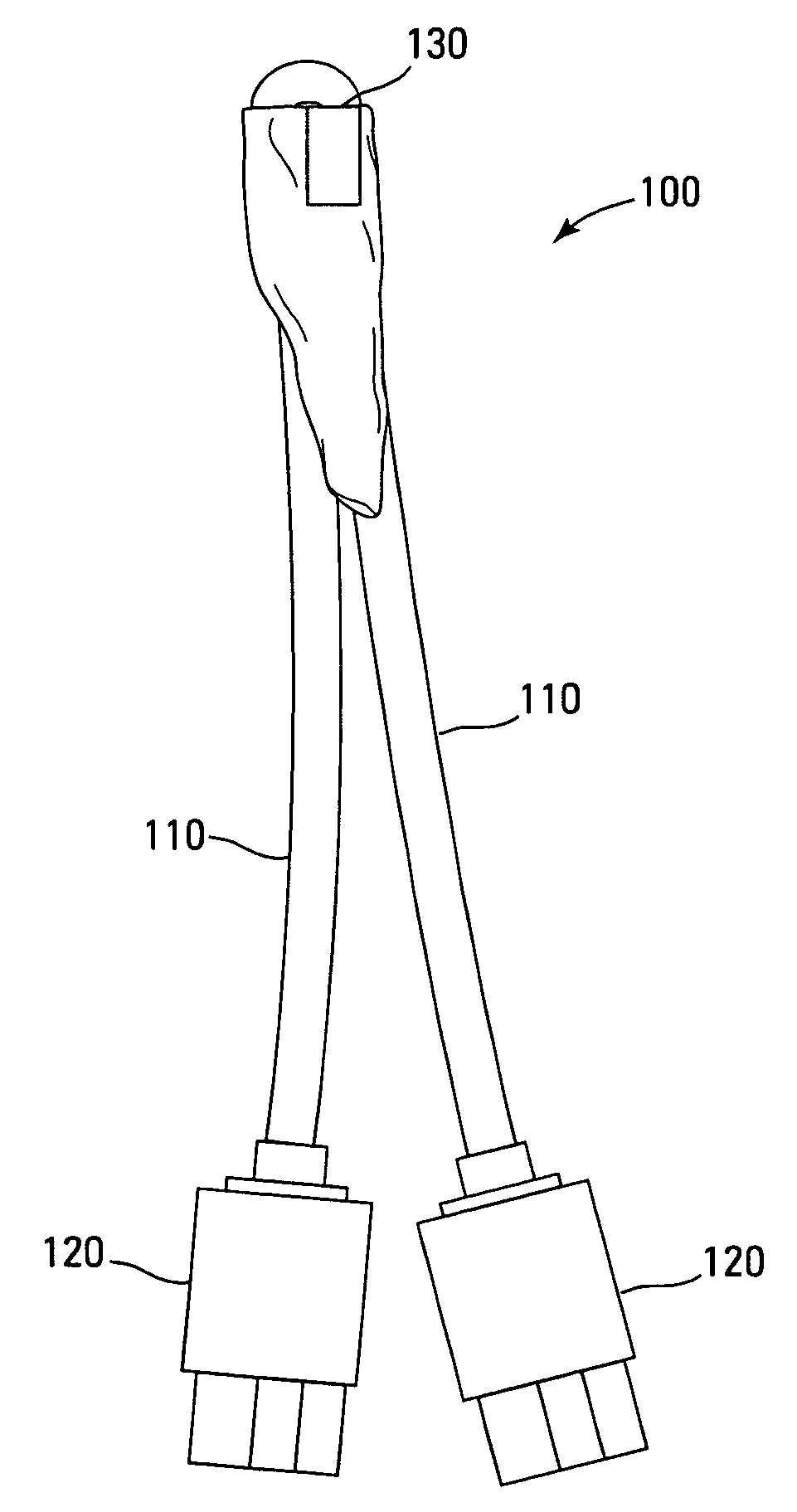
[0014]Accordingly, one embodiment of the present invention comprises the utilization of a single loop or multiple loops of wire with or without a uniform dielectric coating seamlessly attached to two identical coaxial transmission lines of same length. Near and at the coil end, the outer shield of the two coaxial lines are grounded together typically with solder. Because the shield is not electrically connected to the loop wire, signals pick-up by the shield are minimally coupled into the coaxial line. Consequently, the structure is substantially symmetric, thereby increasing the effectiveness of differential signal processing to extract the desired signal. The resultant symmetry provides a near perfect balance of the coil and interconnection structure. Accordingly, the symmetry allows one signal to be subtracted resulting in a zero for common mode electric field stimulus. The symmetry also provides a maximum signal for suitably oriented magnetic field energy. Moreover, adding the signals (instead of subtracting the signals) removes the magnetic field stimulus from the combined signal signature leaving the electric field signal as the measurable. Consequently, the reduction and control of the induction and capacitance expands the useful wide bandwidth in the frequency domain.

Problems solved by technology

Therefore, it is difficult to fabricate a sensor having a wide pass band and with reliable sensitivity throughout the pass band.
Unfortunately, the first optimization leads to a poor response at high frequencies while the latter optimization leads to a limitation of the sensitivity at low frequencies.
Capacitive coupling from shield to shield across the gap exposing the sensor offers limitations to the sensitivity of this device.
In addition, the assembly of these loops are extremely difficult, time consuming, and the probes are difficult to maintain.
The required power meters and receivers utilized to measure the output of these type loop probes are very expensive and hard to use for remote field measurements.
The spurious signals interfere with the measurement process.
Deviations from these exactness result in spurious noise signals that may effect the overall measurement especially as the frequency is increase.

Method used


Image

  • Electric/magnetic field sensor
  • Electric/magnetic field sensor
  • Electric/magnetic field sensor

Examples


Embodiment Construction

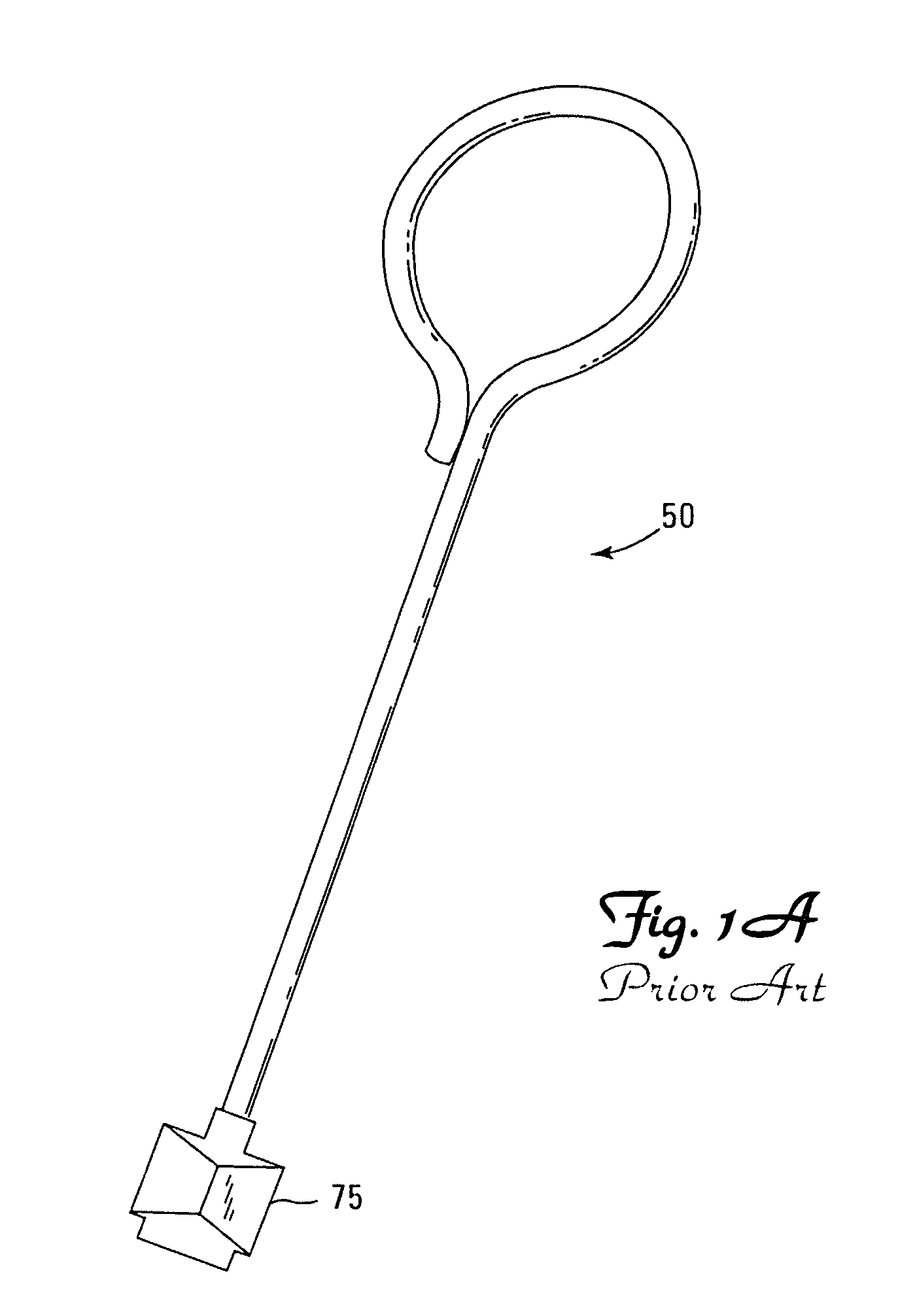
[0022]A conventional differential B-dot makes use of two nearly identical coils spaced closely together in a nearly unique orientation. For packaging purposes, the differential B-dot is housed within a conductive block filled with a dielectric substance. This packaging is not necessary in the differential B-dot design except when trying to eliminate or control proximity effects. Interconnection is accomplished using two pieces of transmission line one for each dot in the differential B-dot set. However, under close scrutiny, the standard and differential B-dot reveals critical limitations. The standard B-Dot suffers from symmetry and ground loop issues. For the differential B-dot to exhibit a spurious noiseless signal, one requires (this assumes that the coil end is terminated on the grounding shield): 1. Identical probes, 2. Identical relative ground line geometry that includes line lengths, bends and twists in the line, line cross-sectional dimensions, line orientations, 3. Line a...


PUM


Abstract

A UNLV novel electric / magnetic dot sensor includes a loop of conductor having two ends to the loop, a first end and a second end; the first end of the conductor seamlessly secured to a first conductor within a first sheath; the second end of the conductor seamlessly secured to a second conductor within a second sheath; and the first sheath and the second sheath positioned adjacent each other. The UNLV novel sensor can be made by removing outer layers in a segment of coaxial cable, leaving a continuous link of essentially uncovered conductor between two coaxial cable legs.

Description

RELATED APPLICATION DATA[0001]This application claims priority from U.S. Provisional Application No. 60 / 605,069, filed Aug. 27, 2004STATEMENT REGARDING FEDERALLY SPONSORED RESEARCH OR DEVELOPMENT[0002]The U.S. Government has a paid-up license in this invention and may have the right in limited circumstances to require the patent owner to license others on reasonable terms as provided for by the terms of DE-FG02-00ER45831 awarded by the Department of Energy.BACKGROUND OF THE INVENTION[0003]1. Field of the Invention[0004]The embodiments of the present invention relate to sensors for measuring magnetic field and electric field phenomena at the same time at the same point in space.[0005]2. Background of the Art[0006]Conventional small magnetic field sensors (commonly referred to as B-dots) consist of a coaxial cable with a coil located at the cable end. The center wire of the coaxial cable extends beyond the outer shield and is shaped in the form of a coil. Typically, the coil may be a ...

Claims


Application Information

Patent Timeline
Patent Type & Authority Patents(United States)
IPC IPC(8): G01R29/12G01R27/04G01R33/00
CPCG01R29/0878
Inventor SCHILL, JR., ROBERT A.POPEK, MARC
Owner THE BOARD OF REGENTS NEVADA SYST OF HIGHER EDUCATION ON BEHALF OF UNLV
Learn More