Class D amplifier

a class d amplifier and amplifier technology, applied in the direction of amplifier protection circuit arrangement, amplifier with semiconductor devices only, amplifier with semiconductor devices, etc., can solve the problems of degrading the quality of the sound regenerated from the speakers, signal input to the power amplifier, and unpleasant sound output from speakers, so as to reduce distortion, reduce amplifier gain, and prevent clipping the effect of digital signal

Active Publication Date: 2009-01-27
YAMAHA CORP
View PDF10 Cites 30 Cited by
  • Summary
  • Abstract
  • Description
  • Claims
  • Application Information

AI Technical Summary

Benefits of technology

[0006]Another object of the invention is to provide a class D amplifier capable of amplifying an input signal with reduced distortion across the entire region of the dynamic range of the input signal and obtaining an output signal at an appropriate level.
[0029]According to this invention, an attenuation command signal is generated to intermittently attenuate the input analog signal when the digital signal is brought into the clip or near-clip state. As a result, the input analog signal to the amplifier part is intermittently thinned on a time axis thus preventing clip on the digital signal. In this case, the input analog signal is intermittently thinned although its waveform is substantially unchanged. This prevents clip without generating waveform distortion.
[0030]Further, according to the invention, when the digital signal is brought into a clip or a near-clip state, the gain control means decreases the gain of the amplifier according to an increase in the level of the input signal so that the peak level of a waveform shown by the digital signal will maintain a certain level. It is thus possible to amplify an input signal with reduced distortion across the entire region of the dynamic range of the input signal and obtain an output signal at an appropriate level.

Problems solved by technology

Such clip must be prevented because, once given to speakers as a load, it is output from the speakers as an unpleasant sound.
The problem is that the signal input to the power amplifier is accompanied by nonlinear distortion caused by the nonlinear characteristic of the level adjuster and the nonlinear distortion appearing on the output signal waveform degrades the quality of the sound regenerated from the speakers.
The problem with the technology disclosed in Patent Reference 1 is that means for controlling the switching amplification stage is required to prevent clip thus resulting in a larger circuit.
Thus, the peak level of the output signal of a class D amplifier may become unnecessarily high.
This does not fully satisfy the needs for audio reproduction at an appropriate sound volume and with reduced distortion.

Method used


Image

  • Class D amplifier
  • Class D amplifier
  • Class D amplifier

Examples


first embodiment

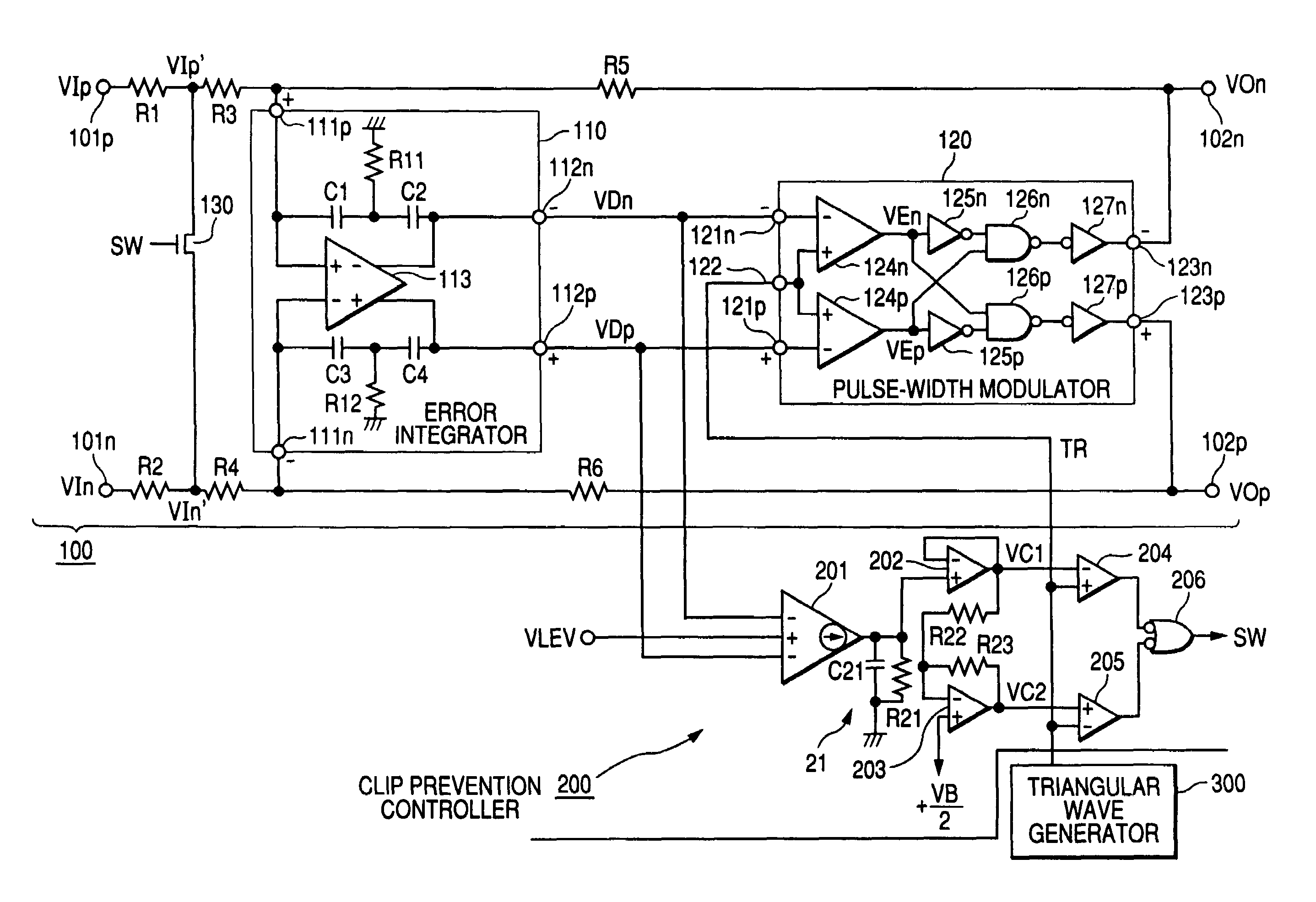
[0045]FIG. 1 is a circuit diagram showing the configuration of a class D amplifier according to the first embodiment of the invention. The class D amplifier roughly includes an amplifier part 100, a clip prevention controller 200, and a triangular wave generator 300. The triangular wave generator 300 is a circuit that generates a triangular wave signal TR of a constant cycle changing in the shape formed by a linear slope within the voltage range of 0V to +VB and supplies the triangular wave signal TR to the amplifier part 100 and the clip prevention controller 200. The amplifier part 100 is a device for generating a digital signal to drive a load based on an input analog signal. Specifically, the amplifier part 100 is a circuit for generating a positive phase digital signal VOp and a negative phase digital signal VOn which are pulse-width-modulated according to the levels of the positive phase analog input signal VIp and the negative phase analog input signal VIn supplied to input t...

second embodiment

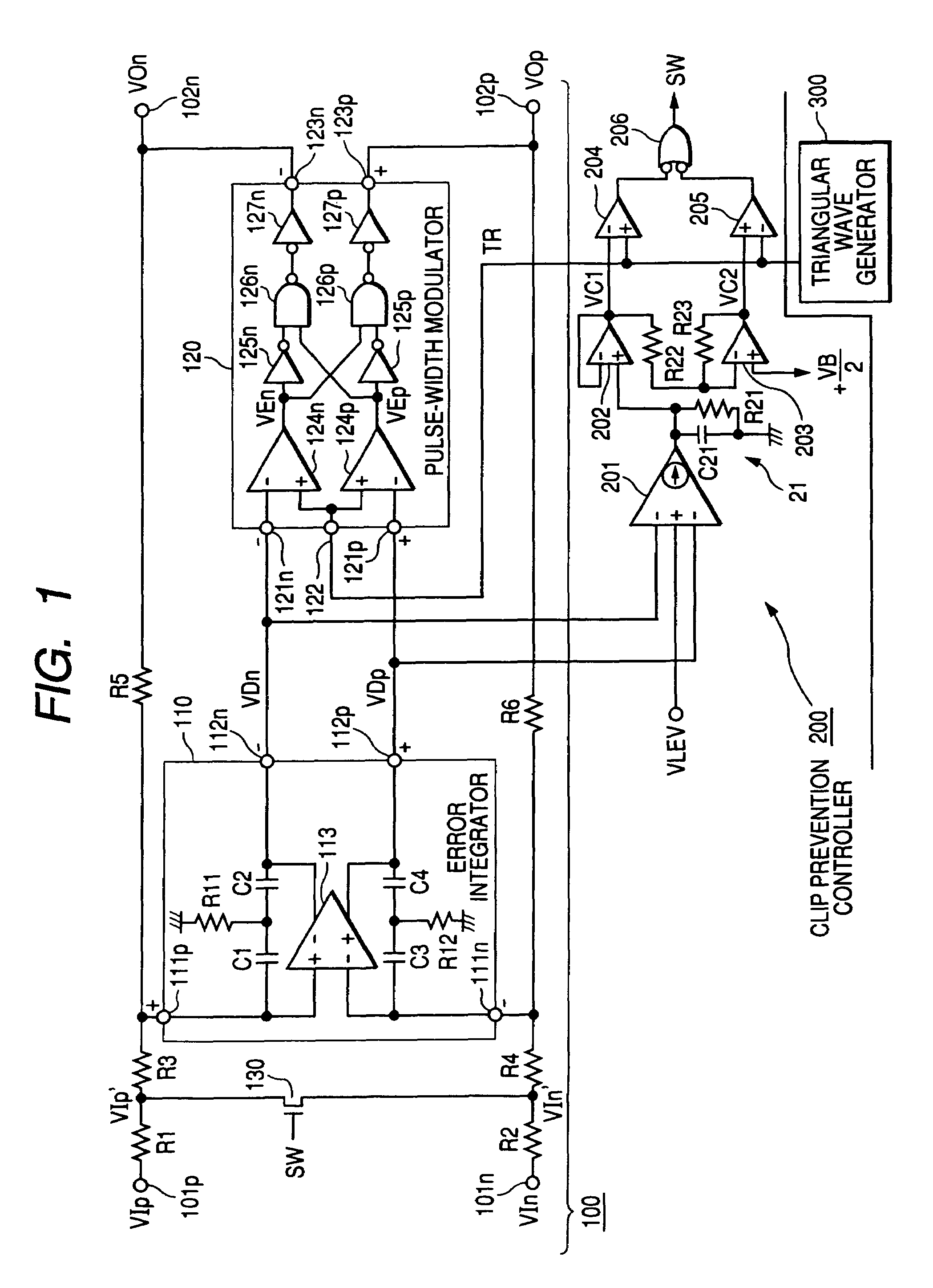
[0072]FIG. 5 is a circuit diagram showing the configuration of a class D amplifier according to the second embodiment of the invention. In the first embodiment (FIG. 1), the output current from the current output comparator 201 is used to generate two comparison voltages VC1 and VC2 crossing the triangular wave signal TR on the higher voltage side and on the lower voltage side. By supplying the first comparison voltage VC1 and the triangular wave signal TR to the comparator 204 and the second comparison voltage VC2 and the triangular wave signal TR to the comparator 205, the attenuation command signal SW as a pulse train is generated.

[0073]In this embodiment, the triangular wave generator 300 in the first embodiment is replaced with a triangular wave generator 300A for outputting positive phase and negative phase triangular wave signals TRp and TRn. Accordingly, the pulse-width modulator 120 in the first embodiment is replaced with a pulse-width modulator 120A for performing pulse-w...

third embodiment

[0076]FIG. 6 is a block diagram showing the configuration of a class D amplifier according to the third embodiment of the invention. In this embodiment, the clip prevention controller 200 in the first embodiment is replaced with a clip prevention controller 200B. In this embodiment, a pulse-shaped timing signal S is supplied to the clip prevention controller 200B from the triangular wave generator 300 with the timing the triangular wave signal TR is at the positive peak and the timing the triangular wave signal TR is at the negative peak.

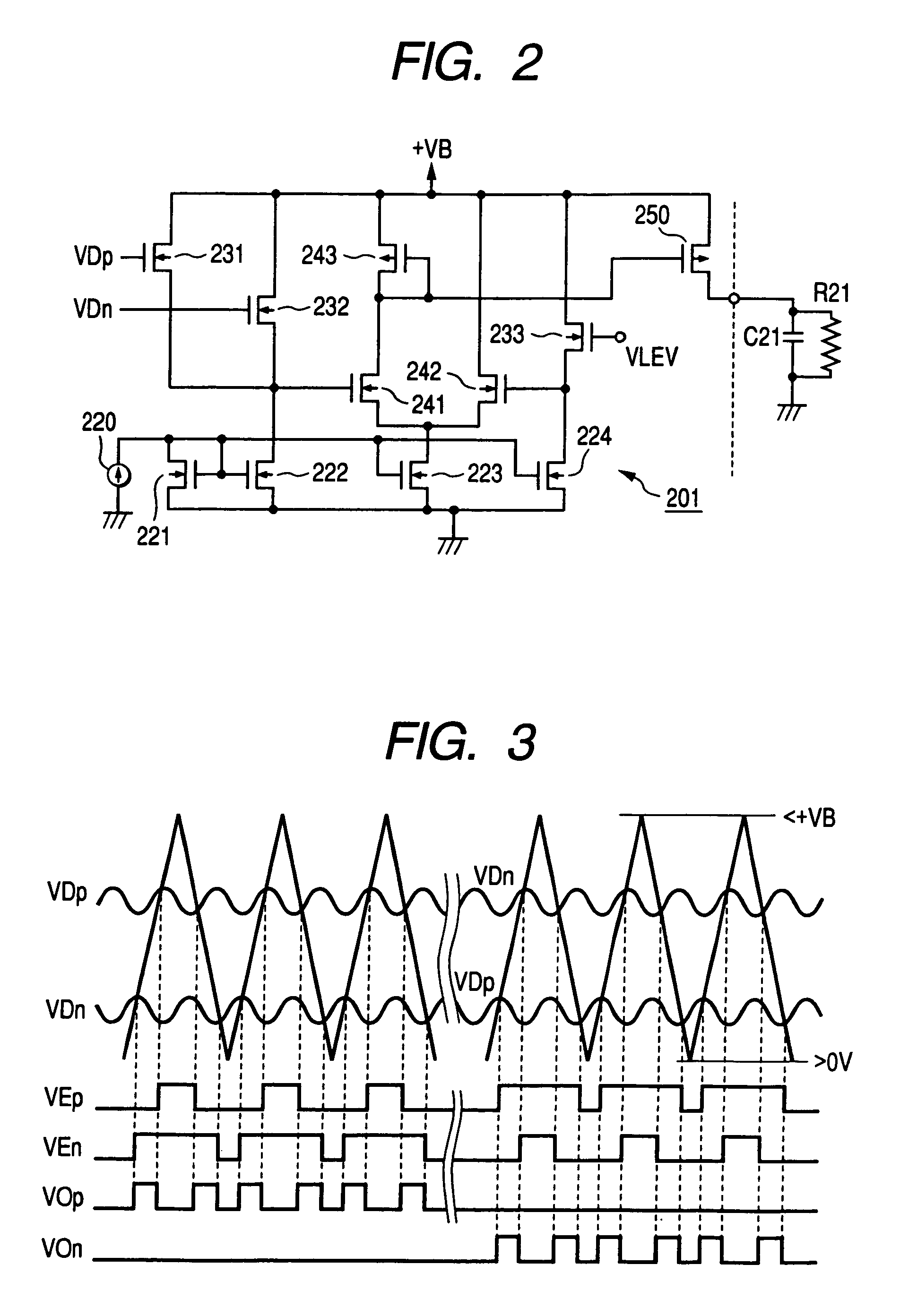
[0077]In case clip is absent, as understood from FIG. 3, the output digital signals VOp and VOn obtained with the timing the triangular wave signal TR is at the positive peak and the timing the triangular wave signal TR is at the negative peak are Low. When clip occurs, the output digital signal VOp or VOn obtained with the timing the triangular wave signal TR is at the positive peak and the timing the triangular wave signal TR is at the negative pe...


PUM


Abstract

A class D amplifier includes: an amplifier that generates a digital signal for driving a load based on an input signal; an attenuator that attenuates the input signal according to an attenuation command signal; and a clip prevention controller that outputs the attenuation command signal to intermittently attenuate the input signal when the digital signal is brought into a clip state or a near-clip state.

Description

BACKGROUND OF THE INVENTION[0001]The present invention relates to a class D amplifier suitable as a power amplifier for an audio system.[0002]The class D amplifier is an amplifier that generates a pulse train with its pulse width or time density modulated according to an input signal and drives a load by way of the pulse train. The class D amplifier is often used as a power amplifier for driving a speaker in an audio system. In this type of power amplifier, clip occurs in an output signal waveform in case the level of an input signal exceeds a proper range. Such clip must be prevented because, once given to speakers as a load, it is output from the speakers as an unpleasant sound. In the related art technology, a level adjuster has been arranged before a power amplifier in order to optimize the amplitude of an input signal to the power amplifier thus preventing occurrence of clip. This technology is disclosed as “related art technology” for example in JP-A-2003-332867.[0003]In the r...

Claims


Application Information

Patent Timeline
Patent Type & Authority Patents(United States)
IPC IPC(8): H03F1/52
CPCH03F3/217H03F2200/66
Inventor MAEJIMA, TOSHIOIWAMATSU, MASAYUKI
Owner YAMAHA CORP
Why Eureka
Try Eureka