Strong substrate alloy and compressively stressed dielectric film for capacitor with high energy density
a dielectric film and capacitor technology, applied in capacitors, capacitor electrodes, electrical equipment, etc., can solve the problems that welding often requires substantial bursts of energy in its operation, and achieve high energy density, high operating electric field, and high power
- Summary
- Abstract
- Description
- Claims
- Application Information
AI Technical Summary
Benefits of technology
Problems solved by technology
Method used
Image
Examples
example 1
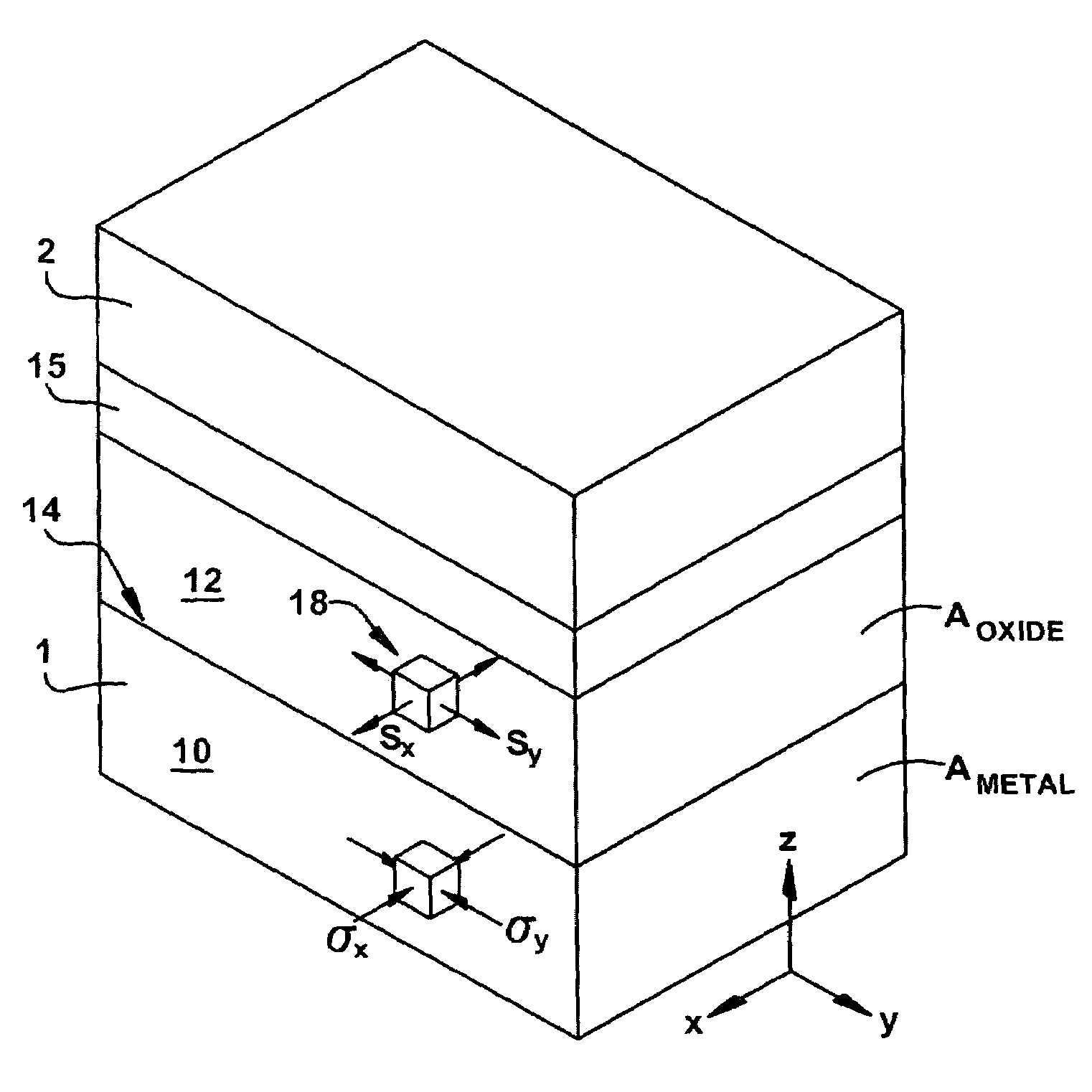
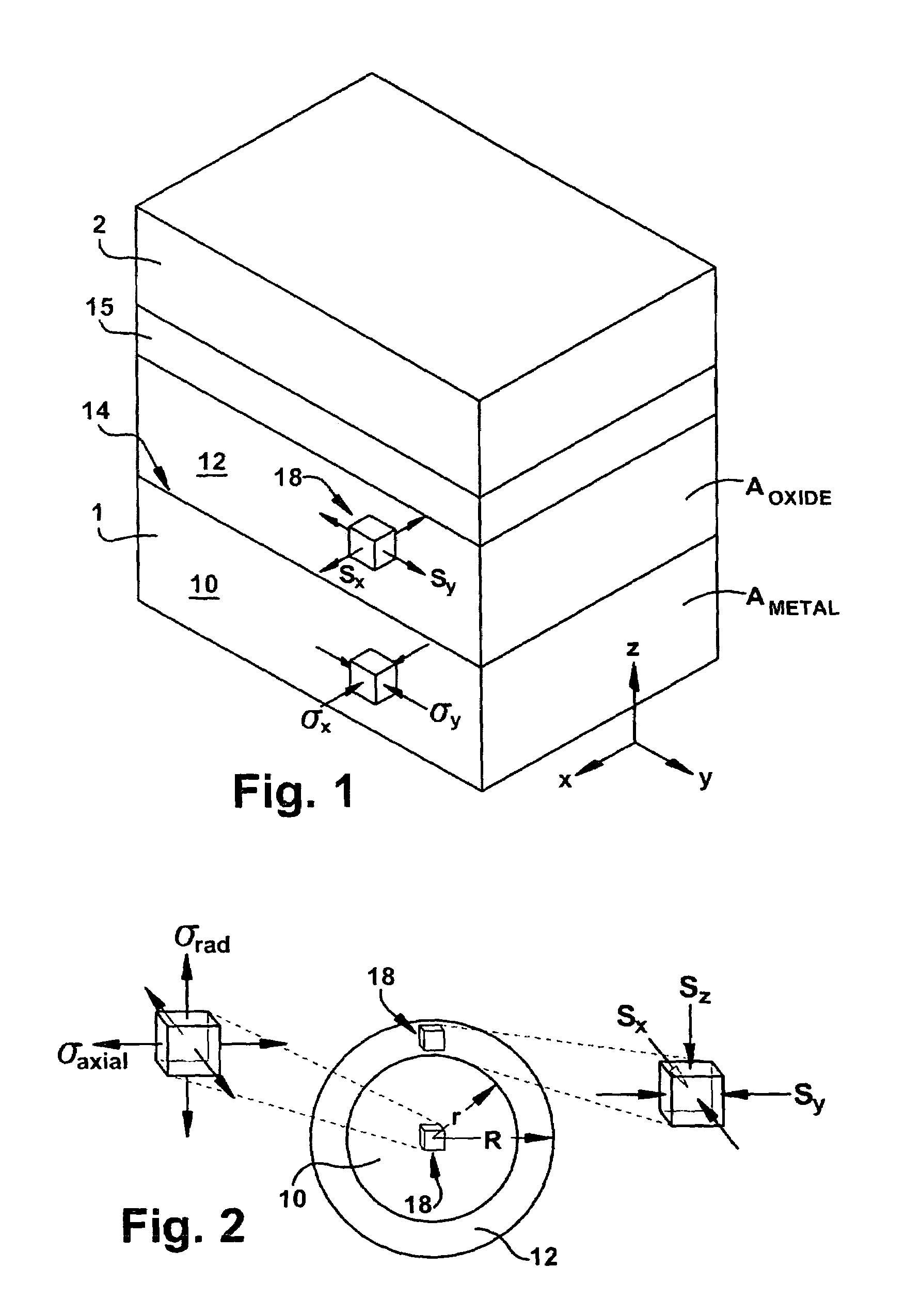
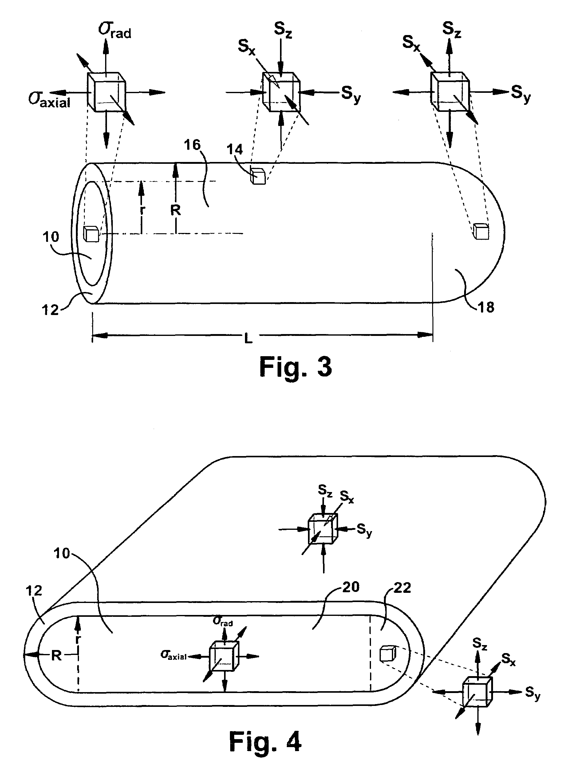
[0200]High purity as-cast tantalum rod is used for a capacitor anode. Tantalum oxide has good dielectric properties under high compressive stress. The tensile yield strength Y of pure tantalum metal is relatively low. It can be about 200 MPa. The compressive yield strength of the Ta2O5 dielectric S can be about 2 GPa. Other property values are as follows:
[0201]
Dielectric strengthξ = 700 V / μmCharge densityq = 0.12 Coulomb / m2Yield strength of tantalumY = 200 MPaCompressive stress in dielectricS = 2 GPa
[0202]In one embodiment, a cylindrical wire anodized to 100 Volt would have a diameter of 6.29 micrometers (2R). The ratio of R / r is determined using Eqn. 16A (substituting the Y value of 200 MPa for σaxial). The energy density of the capacitor anode is then determined using Eqn. 30.
U=ln(1.1)×42 [J / cm3] / 1.1=3.6 J / cm3
This value is relatively low compared to what would be achievable if tantalum had a higher tensile yield strength, such as can be achieved by the alloying and strengthening m...
example 2
[0203]Assume the oxide dielectric has no compressive stress. Then a low tensile strength anode metal will suffice and will allow the capacitor to have a high ratio of oxide volume to metal volume. The maximum energy density is:
U=½ q ξe−1
[0204]However, the charge density q and the dielectric strength ξ of a non-compression-stressed oxide are 100 times lower than in oxide with compressive stress, so the property data are:
[0205]
Useable dielectric strengthξ = 7 V / μmCharge densityq = 0.0012 Coulomb / m2
[0206]In one embodiment, a wire anodized to 100 Volt would have a diameter of 94.2 micrometers.
[0207]In this example the energy density U=1.54×10⁻³ J / cm3 is less than 1 / 1000th the energy density of the low yield strength tantalum capacitor.
example 3
[0208]The property data are the same as in example 1, except the tensile yield strength of tantalum is increased to 500 MPa, either by adding strengthening elements to tantalum, such as nitrogen or carbon, or by strain-hardening. The energy density is:
U=42 [J / cm3]ln(1.25) / 1.25=7.4 J / cm3
[0209]This energy density is more than twice that of the low tensile strength tantalum anode but less than half of what is achievable with ultra high tensile strength tantalum.
PUM
| Property | Measurement | Unit |
|---|---|---|
| tensile yield strength | aaaaa | aaaaa |
| Young's modulus | aaaaa | aaaaa |
| Young's modulus | aaaaa | aaaaa |
Abstract
Description
Claims
Application Information
 - R&D
- Intellectual Property
- Life Sciences
- Materials
- Tech Scout
- Unparalleled Data Quality
- Higher Quality Content
- 60% Fewer Hallucinations
Browse by: Latest US Patents, China's latest patents, Technical Efficacy Thesaurus, Application Domain, Technology Topic, Popular Technical Reports.
© 2025 PatSnap. All rights reserved.Legal|Privacy policy|Modern Slavery Act Transparency Statement|Sitemap|About US| Contact US: help@patsnap.com


