Seal assembly for retractable instrument

a technology of retractable instruments and sealing parts, which is applied in the direction of erasing devices, packaging foodstuffs, packaged goods, etc., can solve the problems of unreliable current sealing elements of retractable instruments, easy loss of outer caps, and inability to meet the needs of use, so as to achieve effective sealing of the nib

Inactive Publication Date: 2009-02-10
SANFORD LP
View PDF358 Cites 20 Cited by
  • Summary
  • Abstract
  • Description
  • Claims
  • Application Information

AI Technical Summary

Benefits of technology

[0007]The present invention improves the reliability and repeatability of a seal assembly for a retractable instrument, e.g., a pen, marker, or the like. Specifically, a seal assembly is coupled to an internal instrument assembly, thereby allowing for constrained movement of the seal assembly when the instrument is protracted and retracted.
[0008]According to one aspect of the present disclosure, a seal assembly for a retractable instrument comprises a base, at least two fingers attached to the base, and a sleeve partially surrounding the base. When the retractable instrument is in a retracted position, the sleeve constrains the fingers such that the fingers are in a fully closed state, thereby effectively sealing the applicator element of the instrument. Protraction of the base relative to the sleeve allows the fingers to open, thereby exposing the applicator element. The seal assembly may be coupled to an applicator element assembly, allowing the seal assembly and the applicator element assembly to be simultaneously protracted. The base of the seal assembly may further include a flange, such that the flange of the base engages an inner flange disposed on an inside surface of a tube of the retractable instrument.
[0010]Protraction of the base and fingers continues until a stop in the nose of the instrument engages a stop of the sleeve, thereby constraining the protraction of the base and fingers and simultaneously allowing the applicator element to completely protract out of the retractable instrument and into an application position. Further, during retraction of the applicator element, a set of stops disposed on the sleeve engages a set of stops disposed on a body of the instrument, thereby preventing further retraction and allowing the fingers to close around and seal the applicator element.
[0012]According to another aspect of the present disclosure, a retractable writing instrument comprises a body and a nose disposed at a first end of the body, and an internal writing assembly disposed within the body and including a nib. The retractable writing instrument further includes a seal assembly coupled to the internal writing assembly; the seal assembly comprises a base, at least two fingers attached to the base, and a sleeve partially surrounding the base. When the retractable writing instrument is in a retracted position, the sleeve constrains the fingers such that the fingers are in a fully closed state, thereby effectively sealing the nib. Protraction of the base relative to the sleeve allows the fingers to open, thereby exposing the nib.
[0013]According to another aspect of the present disclosure, a retractable instrument comprises a body and a nose disposed at a first end of the body and an internal assembly disposed within the body and including an applicator element. The retractable instrument further comprises a seal assembly coupled to the internal assembly, wherein the seal assembly comprises a base, at least two fingers attached to the base, and a sleeve partially surrounding the base. When the retractable instrument is in a retracted position, the sleeve constrains the fingers such that the fingers are in a fully closed state and seal the applicator element, and protraction of the base relative to the sleeve allows the fingers to open, thereby exposing the applicator element.

Problems solved by technology

Such inconveniences include having to use two hands “to uncap and cap a marker pen with the outer cap” and easily losing the outer cap when capping or uncapping an applicator element, e.g., a writing tip.
While capless retractable writing instruments have a superior competitive advantage over a marker or pen having an outer cap, capless instruments have several problems.
For example, the current sealing elements in retractable instruments are unreliable, as they often do not seal after prolonged use, time, or conditioning.
Additionally, such seal assemblies are often unrepeatable, i.e., they do not provide a proper seal after every use.
Additionally, “the assembling process is complicated, time-consuming,” and difficult “to be sped up in mass production.” See, e.g., the '812 patent, col.
The majority of attempts to solve these problems compromise one or both of the reliability and repeatability of the seal.
However, such contact compromises the reliability of the valve seal in that wear results on both the applicator element and valve door.
Additionally, because the applicator element typically deposits fluid upon contact, any interaction between the applicator element and the valve door results in fluid depositing on the sealing features of the valve door.
Repeated interaction results in additional fluid depositing on the sealing features, thereby causing degradation of the seal quality to a point where the seal fails and exposes the applicator element to the ambient atmosphere.
Build-up of fluid deposits due to continued contact between the applicator element and the valve door can further result in binding or sticking of the applicator element and the reservoir holder assembly during retraction.
However, the repeatability of the seal designs that rely on the material elasticity to return back to a closed position all suffer from the effects of cycling and aging.
For example, after prolonged use and exposure to a variety of conditions, the repeatability of the seal is compromised to a point where the applicator element is exposed to the ambient atmosphere.
Designs that rely on mechanical means to provide a repeatable seal appear to provide a more repeatable seal for the retractable instrument; however, the complexity of such designs often results in mechanical failure.
This seal member design suffers from the same fluid, e.g., ink, accumulation problems previously described because the writing tip (34) itself forces the spring clip open while pushing through the seal member.
Also, the writing tip is often damaged while protracting and retracting through the seal member because of the magnitude of the radial force generated by the spring clip.

Method used


Image

  • Seal assembly for retractable instrument
  • Seal assembly for retractable instrument
  • Seal assembly for retractable instrument

Examples


Embodiment Construction

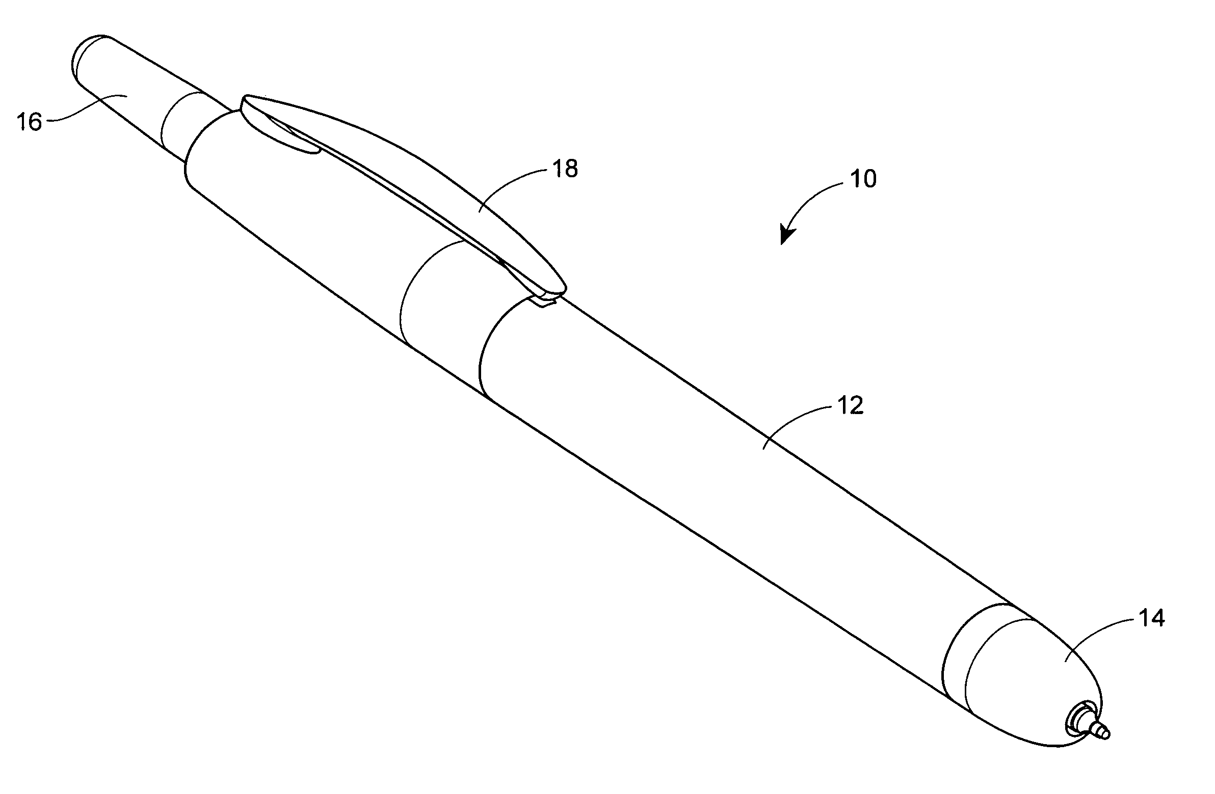
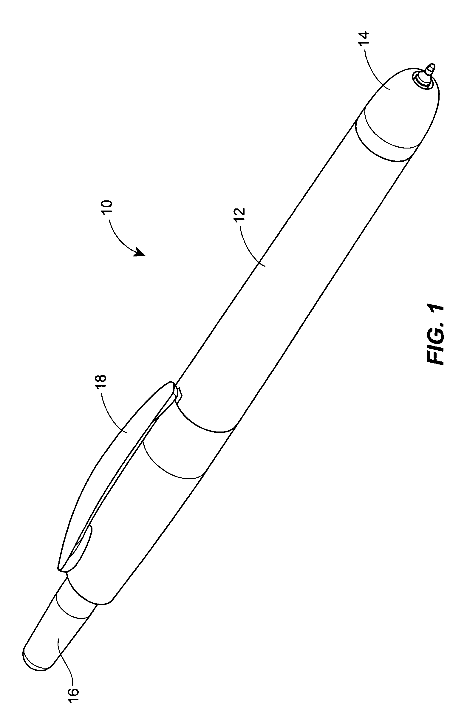
[0023]Referring now to FIG. 1, a retractable instrument 10 is shown. The retractable instrument 10 includes a body 12 and a nose 14, wherein the nose is disposed at a first end of the body 12. A push button or actuator 16 is disposed at a second or actuation end of the body 12, and a clip 18 is disposed on the body 12, as shown, for example, in FIG. 1. More specifically, a well-known knock-type actuation system may be employed that includes a plug having a shaft extending toward the actuation end, and a plunger disposed on the shaft. A spring is disposed between the plunger and the actuator or push button 16. When coupled together, the plug, plunger, spring and actuator or push button 16 provide the well known knock-type actuation system. As is known, by repeatedly pressing the actuator, the actuating system alternately places an applicator element, e.g., a nib, in a retracted position and a protracted or application position, e.g., a writing position. In addition to a knock-type ac...


PUM


Abstract

A seal assembly for a retractable instrument having an applicator element is disclosed, the seal assembly comprising a base, at least two fingers attached to the base, and a sleeve surrounding the base. When the retractable instrument is in a retracted position, the sleeve constrains the fingers such that the fingers are in a fully closed state and seal the applicator element. Protraction of the base relative to the sleeve allows the fingers to open, thereby exposing the applicator element. Thus, the seal assembly opens to expose an applicator element such that the applicator element is in an application position; however, none of the elements of the seal assembly contacts the applicator element to transfer fluid from the applicator element, thereby eliminating potential degradation of the seal.

Description

TECHNICAL FIELD[0001]This disclosure relates generally to seal assemblies for instruments, and, more particularly, to a seal assembly for a retractable instrument, such as a retractable marker.DESCRIPTION OF RELATED TECHNOLOGY[0002]Capless instruments, such as capless retractable markers, have been developed to solve problems and inconveniences associated with retractable instruments having an outer cap. Such inconveniences include having to use two hands “to uncap and cap a marker pen with the outer cap” and easily losing the outer cap when capping or uncapping an applicator element, e.g., a writing tip. See, e.g., U.S. Pat. No. 6,981,812 to (the '812 patent) (providing a description of problems associated with prior art writing instruments using caps). One capless retractable instrument involves hiding a cover of the capless retractable marker pen within a pen tube, and controlling protraction and retraction of the writing tip by an actuating means installed in a top of the pen tu...

Claims


Application Information

Patent Timeline
Patent Type & Authority Patents(United States)
IPC IPC(8): B43K7/12
CPCB43K5/17B43K8/028B43K24/08B43L19/0018B43L19/0068A45D34/04
Inventor DYLKIEWICZ, DAVID A.CHALLMAN, ROBERT G.
Owner SANFORD LP
Why Eureka
Try Eureka