Dust collection assembly of vacuum cleaner

a vacuum cleaner and dust collection technology, applied in the field of vacuum cleaners, can solve the problems of difficult filter cleaning, inconvenient reuse, inability to filter micro-scale foreign objects, etc., and achieve the effects of improving dust collection efficiency, simple construction, and simplifying the dust collection assembly

Inactive Publication Date: 2009-02-10
LG ELECTRONICS INC
View PDF6 Cites 85 Cited by
  • Summary
  • Abstract
  • Description
  • Claims
  • Application Information

AI Technical Summary

Benefits of technology

[0013]An object of the present invention is to provide a dust collection assembly of a vacuum cleaner capable of improving dust collecting efficiency by filtering small and large foreign objects in air using cyclone flow of a large diameter and cyclone flow of a small diameter.
[0014]Another object of the present invention is to provide a dust collection assembly of a vacuum cleaner having simple construction by optimizing arrangement of cyclone flow to simplify a dust collection assembly.
[0015]A further another object of the present invention is to provide a dust collection assembly of a vacuum cleaner capable of reducing manufacturing cost and enhancing convenience in an assembling process by reducing the number of parts constituting a dust collection assembly and making coupling between the parts convenient.
[0020]According to the present invention, filtering performance of the vacuum cleaner improves. Also, the manufacturing process of the dust collecting unit is performed more conveniently and the construction of the dust collection assembly is simple, so that the manufacturing costs reduces and convenience in the assembling process is enhanced.

Problems solved by technology

However, since it is inconvenient to reuse the filter formed of the porous material and it is difficult to clean the filter, in recent years, a cyclone unit has been widely used.
However, the cyclone unit has a problem in that it cannot filter micro-scale foreign objects.
However, when the porous filter is combined with the cyclone unit, the problem of periodically cleaning the filter still remains.
When the foreign objects are implanted in the porous filter, an airflow rate is reduced, thereby deteriorating the operational efficiency of the vacuum cleaner.
In the meantime, since airflow is switched to several directions to produce a plurality of cyclones in the inside of the dust collecting, the inner structure of the multi-cyclone dust collecting unit is complicated.
However, when the dust collecting unit is manufactured by a process of assembling a plurality of parts, the possibility that defect occurs in the finished product increases as much as that and a labor of an operator increases.

Method used


Image

  • Dust collection assembly of vacuum cleaner
  • Dust collection assembly of vacuum cleaner
  • Dust collection assembly of vacuum cleaner

Examples


Embodiment Construction

[0028]Reference will now be made in detail to the preferred embodiments of the present invention, examples of which are illustrated in the accompanying drawings.

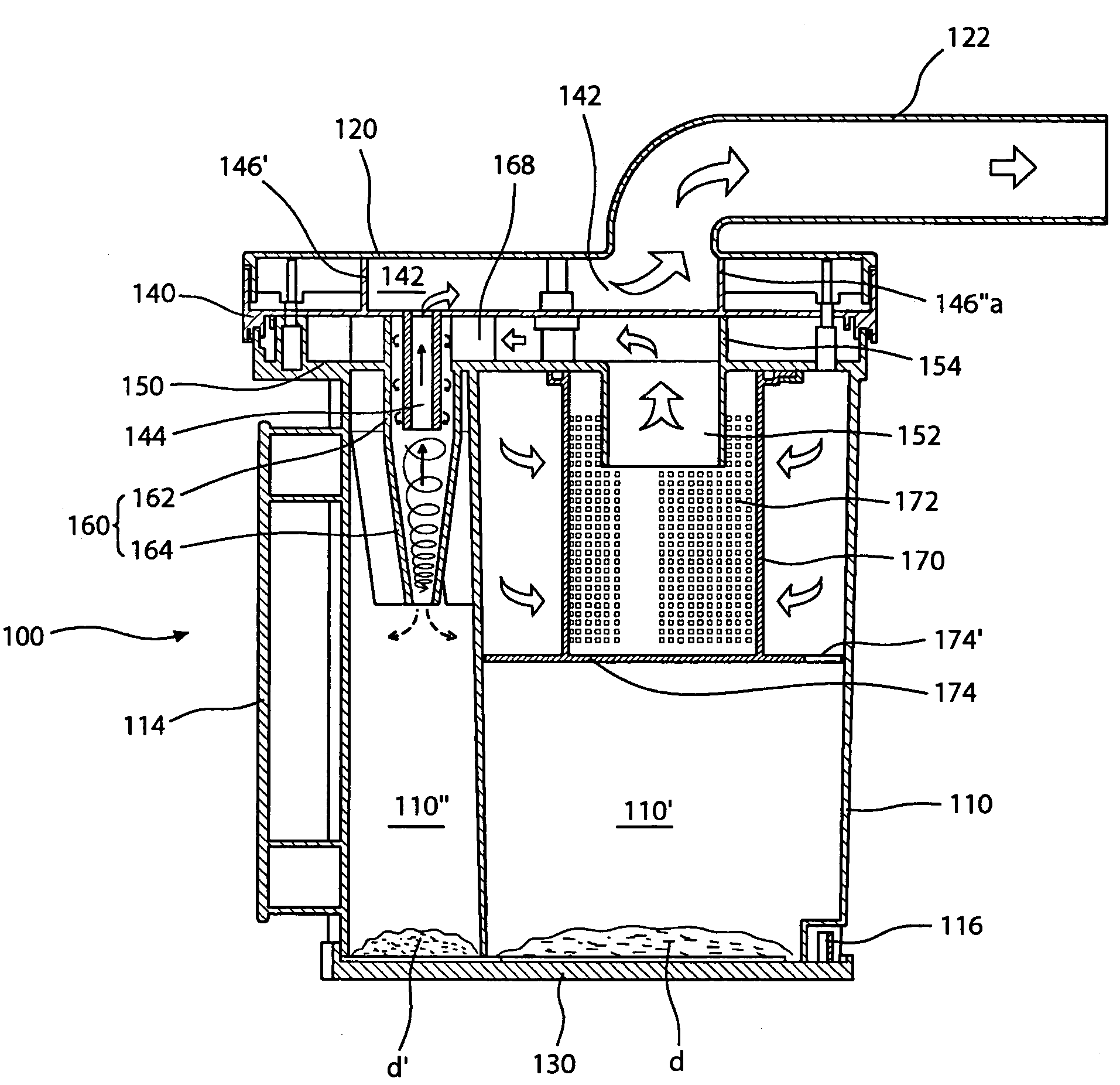
[0029]A dust collection assembly filters and collects foreign objects contained in sucked air. The dust collection assembly can be applied to any type vacuum cleaner regardless of a shape of a vacuum cleaner. For example, the dust collection assembly can be mounted in all types of cleaners including a canister type and a upright type, and applied at least to all types of vacuum cleaners for sucking air and separating foreign objects contained in the sucked air using cyclone airflow produced therein.

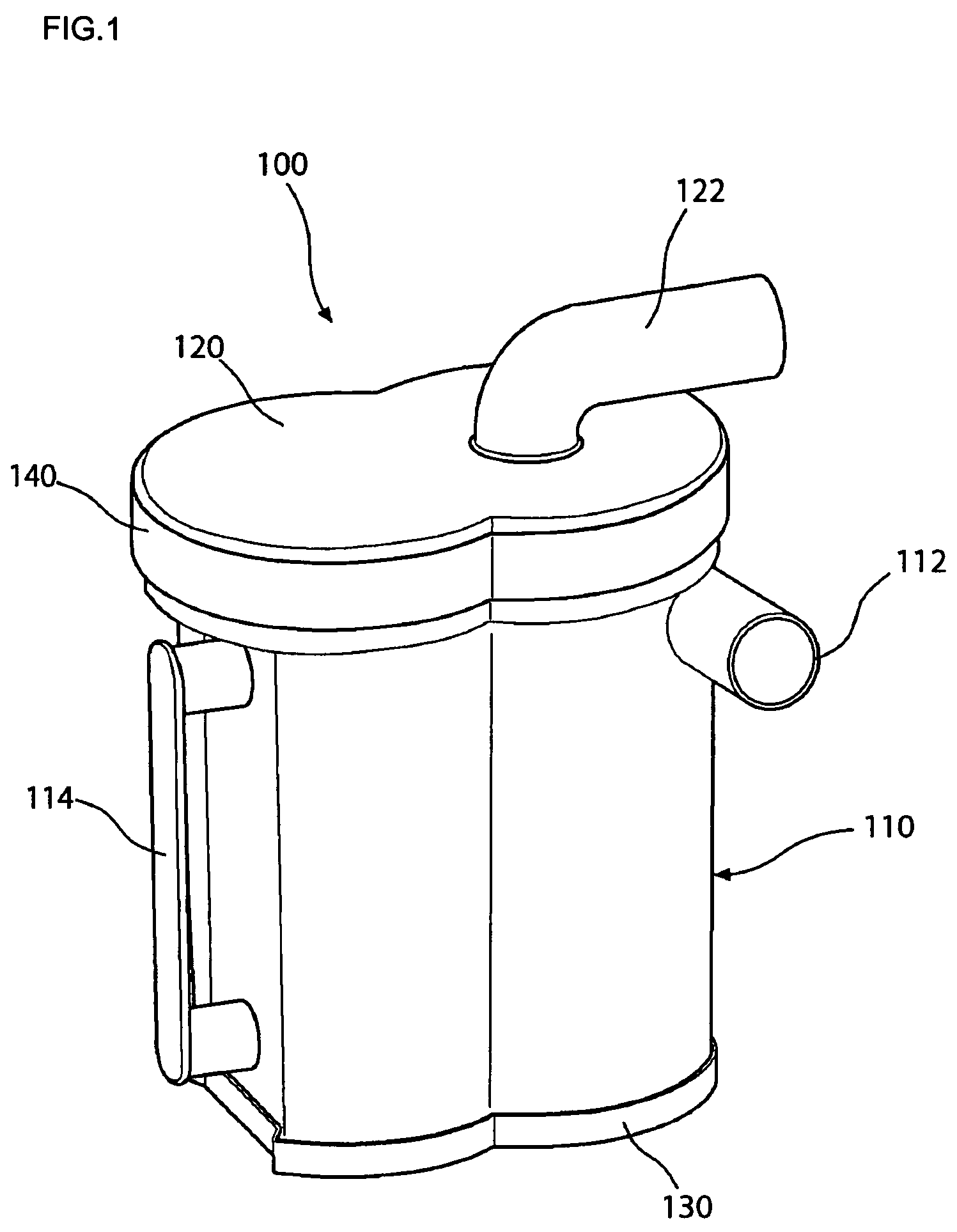
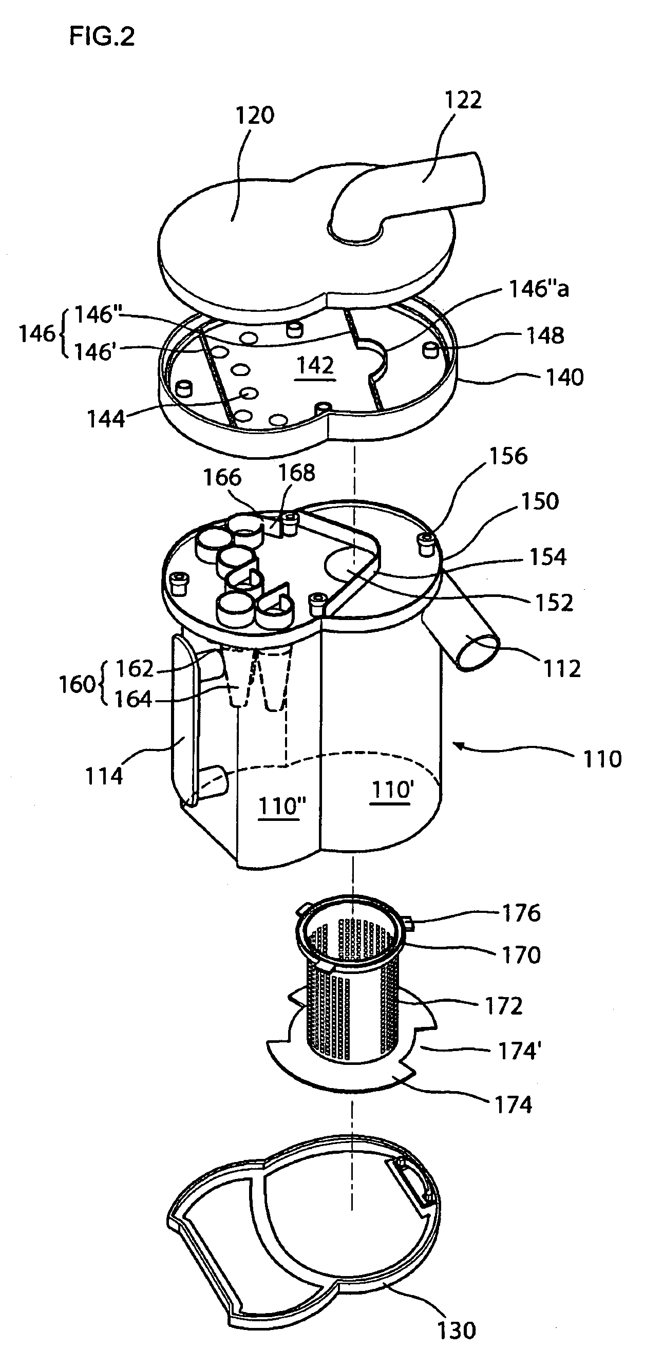
[0030]FIG. 1 is a perspective view of an appearance of a dust collection assembly of a vacuum cleaner according to the present invention, FIG. 2 is an exploded perspective view of a dust collection assembly of a vacuum cleaner according to the present invention, FIG. 3 is a perspective view of the backside of an exhaust guider in ...


PUM

PropertyMeasurementUnit
distanceaaaaaaaaaa
vacuum pressureaaaaaaaaaa
diameteraaaaaaaaaa

Abstract

A dust collection assembly of a vacuum cleaner is provided. The dust collection assembly includes a dust collecting box, a filter, a flow guide unit, an exhaust guider, and an upper cover. The dust collecting box and the flow guide unit are integrally formed in a single body. The dust collecting box includes a first and second dust collecting spaces for collecting foreign objects. The filter is disposed in the inside of the dust collecting space to primarily filter foreign objects during operation of a cyclone. The flow guide unit guides airflow and has small cyclones integrally formed therein, for secondarily filtering the foreign objects in air. The exhaust guider guides airflow and has a plurality of discharge holes through which air filtered by the small cyclone flows. The upper cover is disposed on the upper side of the exhaust guider.

Description

BACKGROUND OF THE INVENTION[0001]1. Field of the Invention[0002]The present invention relates to a vacuum cleaner, and more particularly, to a dust collection assembly of a vacuum cleaner capable of improving dust collecting efficiency by serially installing the first dust collecting member and the second dust collecting member for filtering foreign objects contained in air and being simply manufactured.[0003]2. Description of the Related Art[0004]A vacuum cleaner is used to clean a room or other spaces by sucking air containing foreign objects and filtering the foreign object using vacuum pressure generated therein.[0005]In the meantime, the vacuum cleaner has a dust collecting unit of a predetermined shape mounted within the vacuum cleaner and a filtering device installed in the dust collecting unit, for filtering foreign objects in order to filter foreign objects in sucked air.[0006]The typical filter is formed of porous material so that the foreign objects are filtered while the...

Claims


Application Information

Patent Timeline
Patent Type & Authority Patents(United States)
IPC IPC(8): B01D45/12B01D50/00
CPCA47L9/1625A47L9/1641A47L9/1683B01D50/002B04C5/12B04C5/185B04C5/24Y10S55/03B01D50/20A47L9/10A47L9/16
Inventor JEONG, HOI KILHWANG, MAN TAEKIM, YOUNG HOHWANG, JUNG BAEPARK, MIN
Owner LG ELECTRONICS INC
Why Eureka
Try Eureka