Fiber laser red-green-blue (RGB) light source

a fiber laser and red-green-blue technology, applied in the field of fiber lasers, can solve the problems of lack of directionality, low brightness, and non-laser-based rgb sources

Inactive Publication Date: 2009-02-10
CORNING INC
View PDF24 Cites 11 Cited by
  • Summary
  • Abstract
  • Description
  • Claims
  • Application Information

AI Technical Summary

Benefits of technology

[0006]A first aspect of the invention is red-green-blue (RGB) light source that includes an optical fiber laser configured to emit a near-infrared (NIR) light beam. A wavelength conversion system is optically coupled to the optical fiber laser and has three or fewer non-linear optical (NLO) crystals. The wavelength conversion system is configured to receive the NIR light beam and create therefrom red-, green- and blue-wavelength light beams BR, BG and BB using only single-wavelength light originating from the NIR light beam.

Problems solved by technology

Non-laser-based RGB sources have several shortcomings, including lack of directionality, relatively low brightness, and relatively low conversion efficiency due to their broad spectral band.
Also, such broad-band (i.e., “white light”) sources are limited by a flat power vs. wavelength curve.
This translates into poor wall-plug efficiency.
For those laser-based RGB light sources that include one or two lasers, the designs are relatively complex and non-compact.

Method used


Image

  • Fiber laser red-green-blue (RGB) light source
  • Fiber laser red-green-blue (RGB) light source
  • Fiber laser red-green-blue (RGB) light source

Examples


generalized embodiment

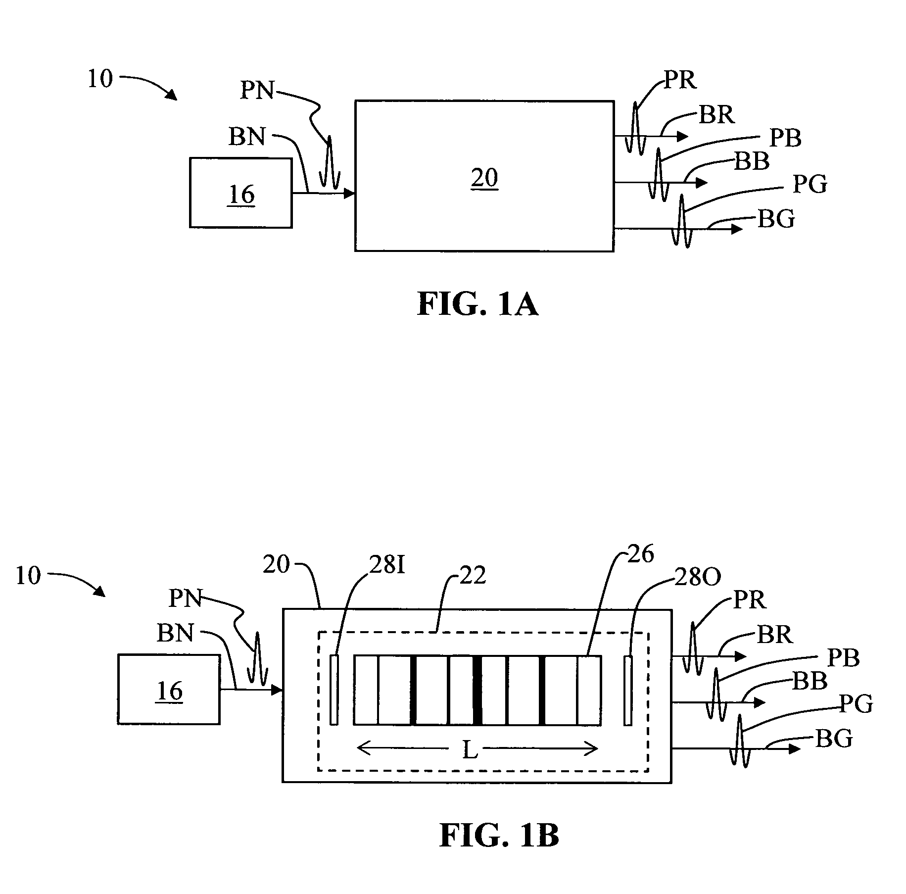
[0025]FIG. 1A is schematic diagram of a generalized embodiment of a fiber-laser RGB light source (“FL-RGB source”) 10 according to the present invention. FL-RGB source 10 includes a fiber laser 16 optically coupled to a wavelength conversion system 20 having an input end 20I and an output end 20O. Fiber laser 16 outputs a light beam BN having a near-infrared (NIR) wavelength λN. In an example embodiment, NIR light beam BN has a wavelength λN=1036 nm. Also in an example embodiment, light beam BN is made up of NIR light pulses PN (i.e., in the case where fiber laser 16 is a pulsed light source). Example embodiments of fiber laser 16 are discussed in greater detail below.

[0026]Wavelength conversion system 20 is adapted to receive at input end 20I NIR light beam BN from fiber laser 16 and generate therefrom red (λR), green (λG) and blue (λB) output beams BR, BG and BB, respectively, at output end 20O. In an example embodiment, only light originating from NIR output beam BN is used to fo...

example single

Crystal Embodiment

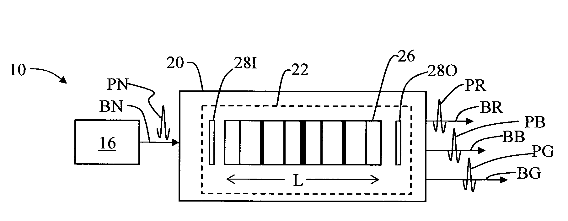
[0028]FIG. 1B is a schematic diagram of an example embodiment of a “single crystal” FL-RGB source 10, wherein wavelength conversion system 20 includes a single NLO unit 22. In an example embodiment, NLO unit 22 includes a single crystal, and in particular consists of an optical parametric oscillator (OPO) having a single periodically poled crystal 26 surrounded at its input and output ends by respective input and output end-mirrors 28I and 28O. Crystal 26 has a poling pattern that contains three poling spatial periods that result in the generation of RGB wavelengths λR, λG and λB, in analogy to a time signal being a sum of three sinusoidal time signals. Also generated in the non-linear optical process in the OPO is mid-infrared (MIR) light of wavelength λM. In an example embodiment, λM=3284 nm.

[0029]In this single-crystal example embodiment, input end-mirror 28I mirror is antireflection (AR) coated at λN (e.g., λN=1036 nm) and high-reflection (HR) coated at λR, λG,...

example two

Crystal Embodiment

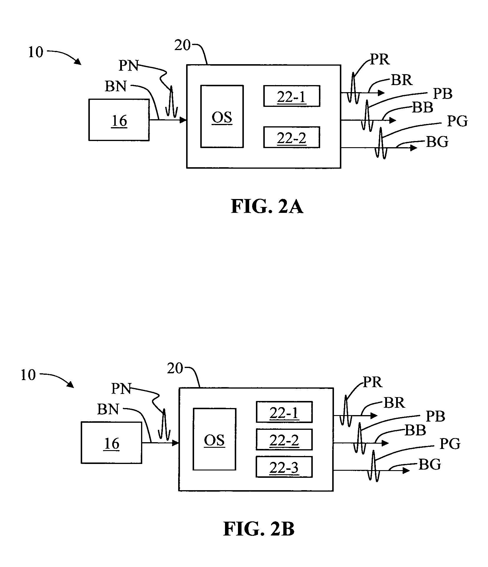
[0031]FIG. 2A is a schematic diagram illustrating an example embodiment of a “two crystal” FL-RGB source 10, wherein wavelength conversion system 20 includes an optical system OS and two non-linear optical (NLO) units 22-1 and 22-2. The two NLO units 22-1 and 22-2 are operably arranged relative to optical system OS to receive NIR light beam BN and generate therefrom red, green and blue output beams BR, BG and BB made up of respective light pulses PR, PG and PB. In an example embodiment, optical system OS is configured relative to the first and second NLO units 22-1 and 22-2 so as to provide an optical path over which only light originating from NIR output beam BN is used to form the red-, green- and blue-wavelength light beams BR, BG and BB. That is to say, FL-RGB source 10 does not utilize any other light source besides that from fiber laser 16 to create light beams BR, BG and BB.

[0032]FIG. 3A is a more detailed schematic diagram illustrating an example embodiment...


PUM

PropertyMeasurementUnit
NIR wavelengthaaaaaaaaaa
average power PRaaaaaaaaaa
reflectivity R4aaaaaaaaaa

Abstract

An RGB light source that uses an optical fiber laser to generate a near-infrared (NIR) output light beam, and a wavelength conversion system that receives the output NIR light beam and forms therefrom red, green and blue light beams. The fiber laser includes multiple stages, wherein the first stage includes a solid-state laser to generate an initial NIR light beam. One or more subsequent stages operate to amplify the NIR light beam to form a relatively high-average-power output NIR light beam. Only light from the fiber laser is used to generate the red, green and blue-wavelength output light beams. The wavelength conversion system includes three or fewer non-linear optical (NLO) units. A color display that utilizes the RGB light source is also disclosed.

Description

FIELD OF THE INVENTION[0001]The present invention relates generally to fiber lasers, and in particular relates to a fiber laser-based red-green-blue (RGB) light source.BACKGROUND OF THE INVENTION[0002]The red, green and blue (RGB) color model involves combining different proportions of red, blue and green light to produce other colors. This model is used in many different types of color displays, such as cathode-ray-tube monitors, liquid crystal displays, and plasma-based displays. In the typical color display, each pixel is configured to combine varying amounts of red, green and blue to create a wide range of colors. The 1931 CIE color space, created by the International Commission on Illumination in 1931, is a useful and convenient way to determine the range of colors available based on specific red, blue and green wavelengths. An example set of RGB wavelengths is λR=630 nm, λG=532 nm and λB=465 nm, respectively.[0003]Each type of color display uses some kind of light source to ge...

Claims


Application Information

Patent Timeline
Patent Type & Authority Patents(United States)
IPC IPC(8): G02F2/02H01S3/10
CPCG02F1/3532G02F1/3558H01S3/0092H01S3/06754H01S3/2308
Inventor BAUCO, ANTHONY SEBASTIAN
Owner CORNING INC
Why Eureka
Try Eureka