Laser processing device

a technology of laser processing and laser processing, which is applied in the direction of manufacturing tools, instruments, optical elements, etc., can solve problems such as the change of the light-converging point position

Active Publication Date: 2009-02-10
HAMAMATSU PHOTONICS KK
View PDF11 Cites 119 Cited by
  • Summary
  • Abstract
  • Description
  • Claims
  • Application Information

AI Technical Summary

Benefits of technology

[0005]In view of such circumstances, it is an object of the present invention to provide a laser processing apparatus which can suppress the positional fluctuation in laser light converging position during laser processing to a low level.
[0007]In this laser processing apparatus, laser light having a beam size enlarged by the beam expander is emitted to the second light-transmitting hole of the stop member, so that the outer peripheral part of the laser light greater than the second light-transmitting hole is cut, whereby the laser light passes through the second light-transmitting hole while narrowing the beam size. The laser light having passed the second light-converging hole is emitted to the first light-transmitting hole of the lens holder, whereas the laser light having passed the first light-transmitting hole is converged by the condenser lens. The light-converging point is positioned within a wafer-like (i.e., thin, flat) object to be processed, so as to form a modified region by multiphoton absorption within the object. When a stop member is disposed on an optical path of laser light connecting the beam expander and the first light-transmitting hole to each other, the amount of laser light cut by the surrounding part of the first light-transmitting hole can be made smaller than that in the case where the laser light having a beam size enlarged by the beam expander is directly emitted to the first light-transmitting hole of the lens holder, whereby the heating of the lens holder by the cut laser light can be suppressed. Also, even when the stop member is heated by the part of laser light cut by the surrounding part of the second light-transmitting hole, heat is prevented from being transmitted from the stop member to the lens holder, since the stop member is separated from the lens holder. Therefore, the positional fluctuation in light-converging point of laser light mainly due to the heating of the lens holder during laser processing can be suppressed to a low level, whereby the modified region can be formed accurately at a predetermined position within the wafer-like object to be processed.
[0008]When the laser light emitted from the beam expander is substantially parallel light, it will be preferred if the second light-transmitting hole has a diameter not greater than that of the first light-transmitting hole. When the laser light emitted from the beam expander is completely parallel light, the diameter of laser light having passed the second light-transmitting hole of the stop member can be made equal to that of the first light-transmitting hole if the diameter of the second light-transmitting hole and that of the first light-transmitting hole are the same. When the laser light emitted from the beam expander is substantially parallel light but slightly expands, the laser light can hardly be incident on the surrounding part of the first light-transmitting hole if the diameter of the second light-transmitting hole is made smaller than that of the first light-transmitting hole in view of the expansion of the laser light. Hence, while allowing the condenser lens to exhibit its light-converging characteristic to the maximum, the amount of laser light cut by the surrounding part of the first light-transmitting hole can substantially be eliminated, whereby the heating of the lens holder can further be suppressed. Here, the substantially parallel light encompasses completely parallel light as well.
[0010]ϕL⁢{M⁡(ϕ0+2⁢d1⁢tan⁢⁢θ0)+2⁢d2⁢tan⁢⁢θ1}M⁡(ϕ0+2⁢d1⁢tan⁢⁢θ0)+2⁢(d2+d3)⁢tan⁢⁢θ1≥ϕs.When the laser light emitted from the beam expander is divergent light, the laser light can hardly be incident on the surrounding part of the first light-transmitting hole if the diameter φL of the first light-transmitting hole and the diameter φS of the second light-transmitting hole satisfy the above-mentioned relationship. Hence, the amount of laser light cut by the surrounding part of the first light-transmitting hole can substantially be eliminated, whereby the heating of the lens holder can further be suppressed.
[0012]ϕL⁢{M⁡(ϕ0+2⁢d1⁢tan⁢⁢θ0)-2⁢d2⁢tan⁢⁢θ1}M⁡(ϕ0+2⁢d1⁢tan⁢⁢θ0)-2⁢(d2+d3)⁢tan⁢⁢θ1≥ϕs.When the laser light emitted from the beam expander is convergent light, the laser light can hardly be incident on the surrounding part of the first light-transmitting hole if the diameter φL of the first light-transmitting hole and the diameter φS of the second light-transmitting hole satisfy the above-mentioned relationship. Hence, the amount of laser light cut by the surrounding part of the first light-transmitting hole can substantially be eliminated, whereby the heating of the lens holder can further be suppressed.

Problems solved by technology

This yields a fear of the laser head and condenser lens expanding, and so forth, thereby changing the light-converging point position of laser light with respect to the object to be processed.
Such a change in light-converging point position becomes a particularly severe problem in laser processing in which a modified region is formed by multiphoton absorption within a wafer-like object to be processed.

Method used


Image

  • Laser processing device
  • Laser processing device
  • Laser processing device

Examples


Embodiment Construction

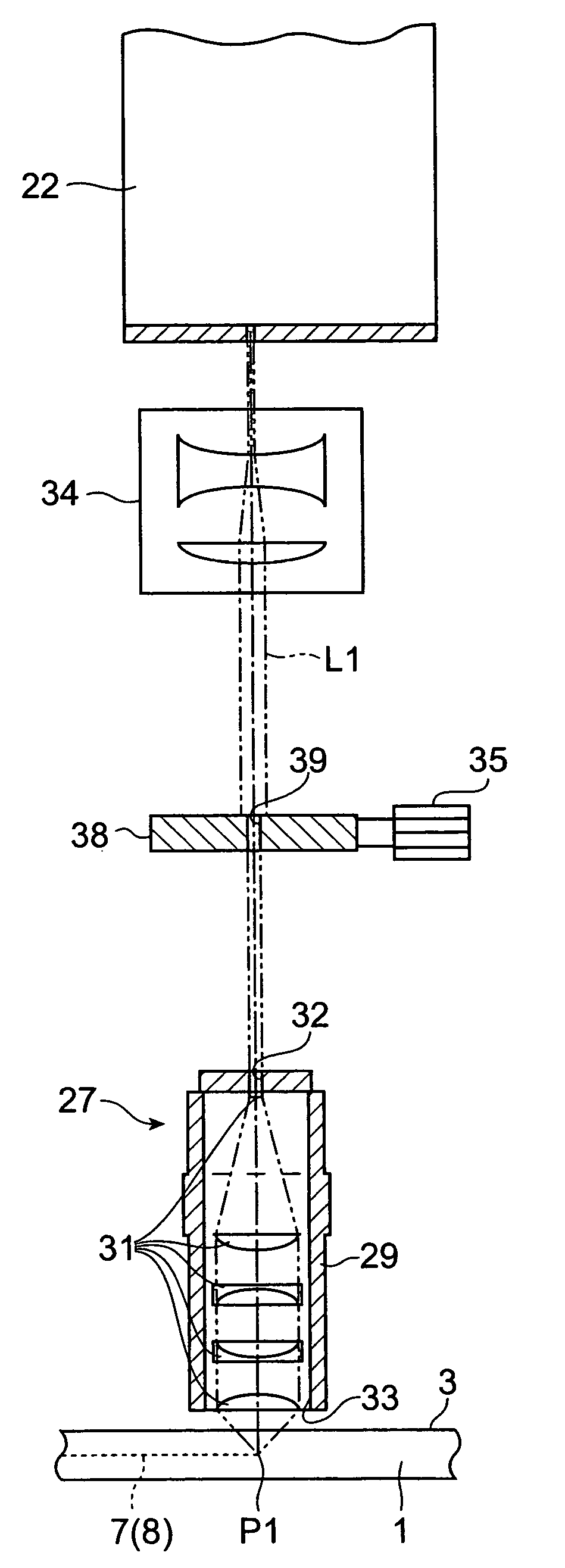
[0031]In the following, a preferred embodiment of the laser processing apparatus in accordance with the present invention will be explained in detail with reference to the drawings.

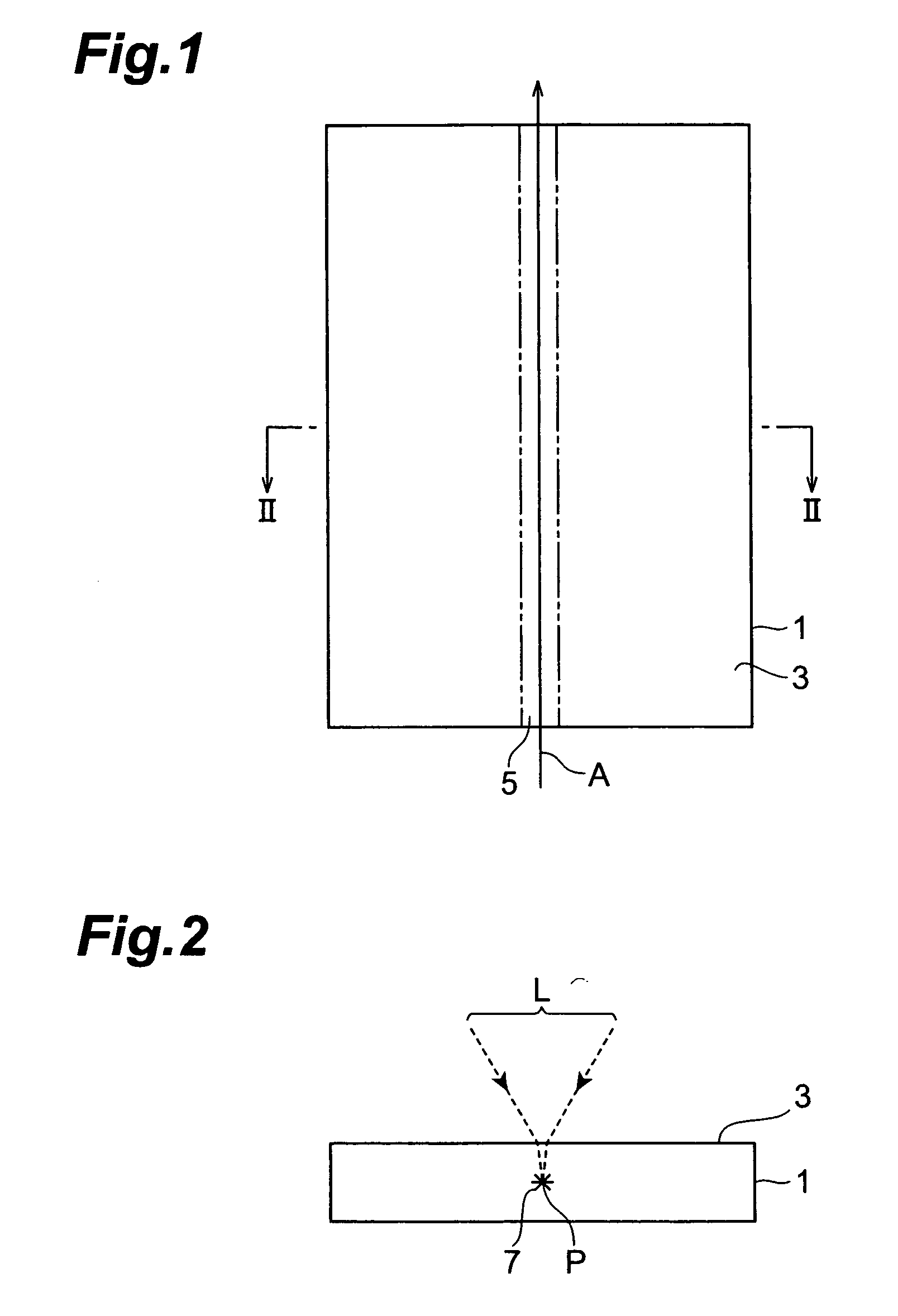
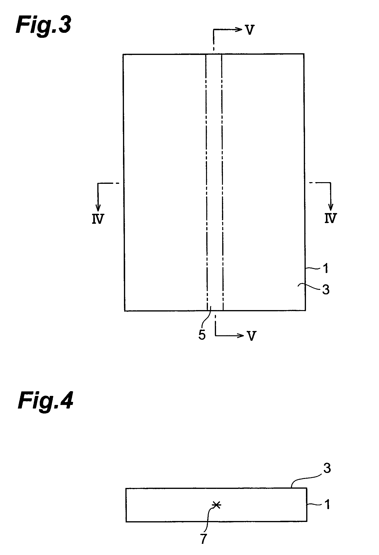
[0032]The laser processing apparatus in accordance with this embodiment irradiates a wafer-like object to be processed while locating a light-converging point within the object, so as to form a modified region by multiphoton absorption within the object. Therefore, before explaining the laser processing apparatus in accordance with this embodiment, the forming of a modified region by the multiphoton absorption will be explained.

[0033]A material becomes transparent when its absorption bandgap EG is greater than photon energy hv. Hence, a condition under which absorption occurs in the material is hv>EG. However, even when optically transparent, the material generates absorption under a condition of nhv>EG (where n=2, 3, 4, . . . ) if the intensity of laser light becomes very high. This phenomenon is known a...


PUM

PropertyMeasurementUnit
thicknessaaaaaaaaaa
sizeaaaaaaaaaa
thicknessaaaaaaaaaa

Abstract

A laser processing apparatus which can suppress the positional fluctuation in light-converging point of laser light during laser processing is provided. On an optical path of laser light L1 connecting a beam expander 34 and a first light-transmitting hole 32 of a lens holder 29 to each other in a laser processing apparatus 20, a stop member 38 including a second light-transmitting hole 39 having the same diameter as that of the first light-transmitting hole 32 is disposed. Hence, the amount of laser light L1 cut by the surrounding part of the first light-transmitting hole 32 can substantially be eliminated, whereby the lens holder 29 can be prevented from being heated upon irradiation with the laser light L1. Also, even when the stop member 38 is heated by the laser light L1 cut by the surrounding part of the second light-transmitting hole 39, heat is prevented from being transmitted from the stop member 38 to the lens holder 29, since the stop member 38 is separated from the lens holder 29. Therefore, the positional fluctuation in light-converging point P1 of the laser light L1 during laser processing can be suppressed to a low level.

Description

TECHNICAL FIELD[0001]The present invention relates to a laser processing apparatus for forming a modified region by multiphoton absorption within a wafer-like object to be processed.BACKGROUND ART[0002]Laser processing apparatus which perform processing such as fusion cutting by irradiating an object to be processed with laser light have conventionally been known. In general, this kind of laser processing apparatus includes a laser head provided with a condenser lens for converging laser light onto an object to be processed, whereas a light-transmitting hole is provided on the laser light entrance side of the laser head as an entrance pupil for allowing the laser light incident on the converging lens to have a fixed diameter (see, for example, Japanese Patent Application Laid-Open No. HEI 5-212571 and Japanese Utility Model Application Laid-Open No. HEI 3-18979).DISCLOSURE OF THE INVENTION[0003]In the laser processing apparatus mentioned above, laser light having a beam size greater...

Claims


Application Information

Patent Timeline
Patent Type & Authority Patents(United States)
IPC IPC(8): G02B9/00B23K26/06B23K26/046B23K26/064B23K26/066B23K101/40B28D1/22B28D5/00H01S3/00
CPCB23K26/0057B23K26/0656B23K26/1458B23K26/4075B28D1/221B23K2201/40B23K26/1462B23K26/066B23K26/40B23K26/53B23K2101/40B23K2103/50B23K26/04B28D5/00
Inventor FUKUYO, FUMITSUGUFUKUMITSU, KENSHIOSAJIMA, TETSUYA
Owner HAMAMATSU PHOTONICS KK
Why Eureka
Try Eureka