[0005] In view of such circumstances, it is an object of the present invention to provide a laser processing apparatus which can suppress the positional fluctuation in laser light converging position during laser processing to a low level.
[0007] In this laser processing apparatus, laser light having a
beam size enlarged by the
beam expander is emitted to the second light-transmitting hole of the stop member, so that the outer
peripheral part of the laser light greater than the second light-transmitting hole is
cut, whereby the laser light passes through the second light-transmitting hole while narrowing the
beam size. The laser light having passed the second light-converging hole is emitted to the first light-transmitting hole of the lens holder, whereas the laser light having passed the first light-transmitting hole is converged by the condenser lens. The light-converging point is positioned within a
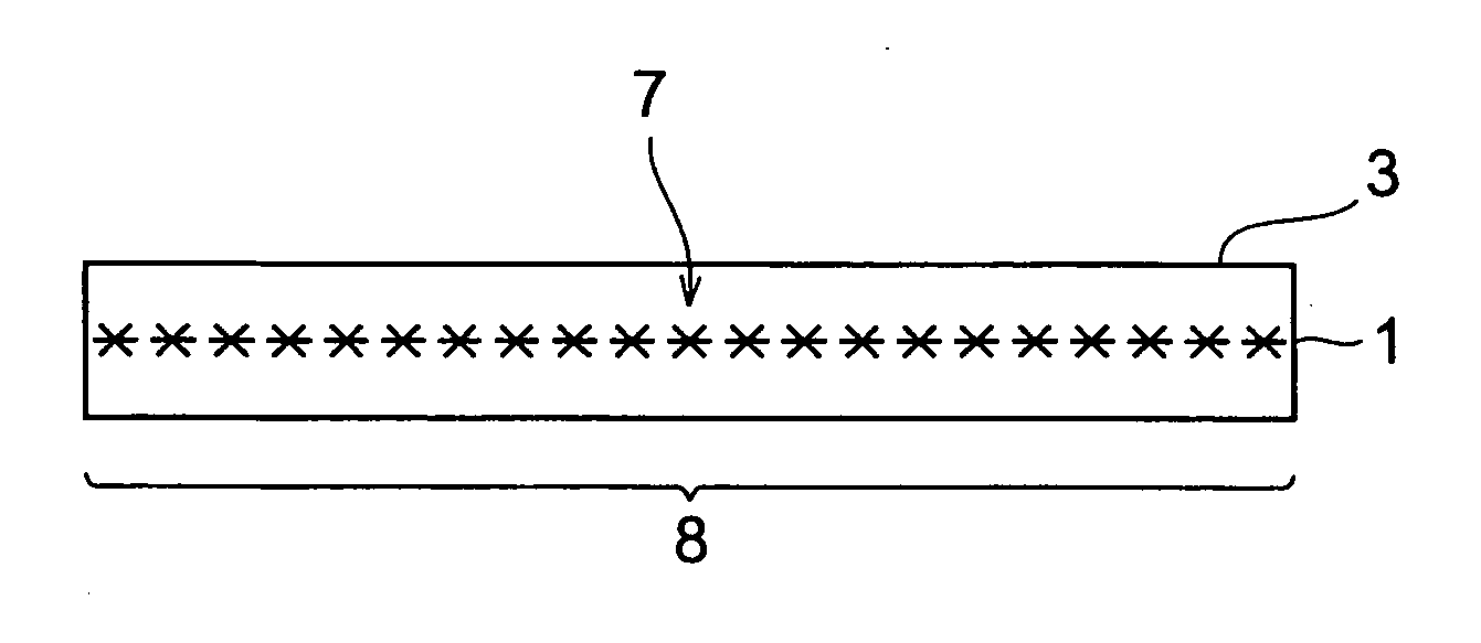
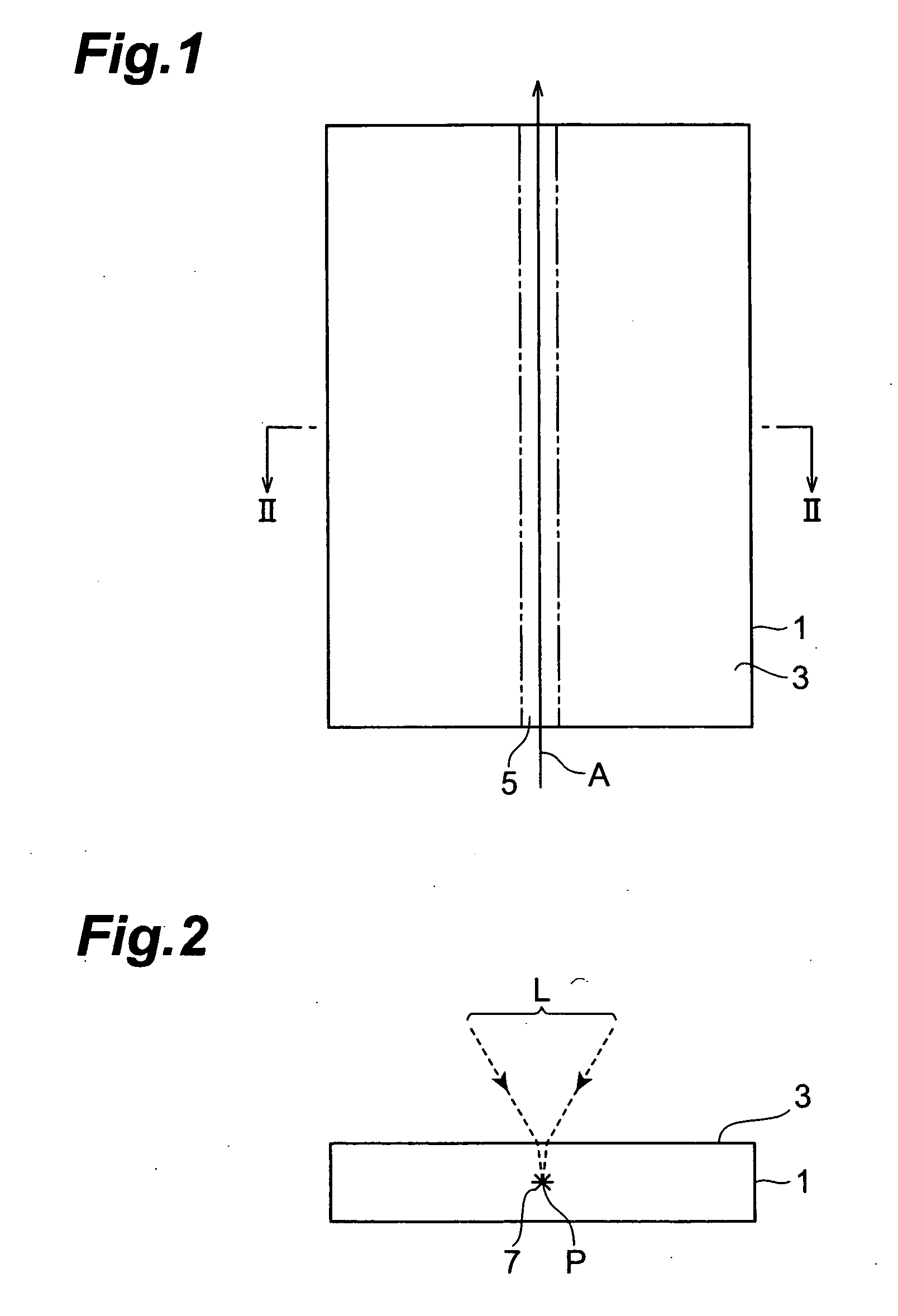
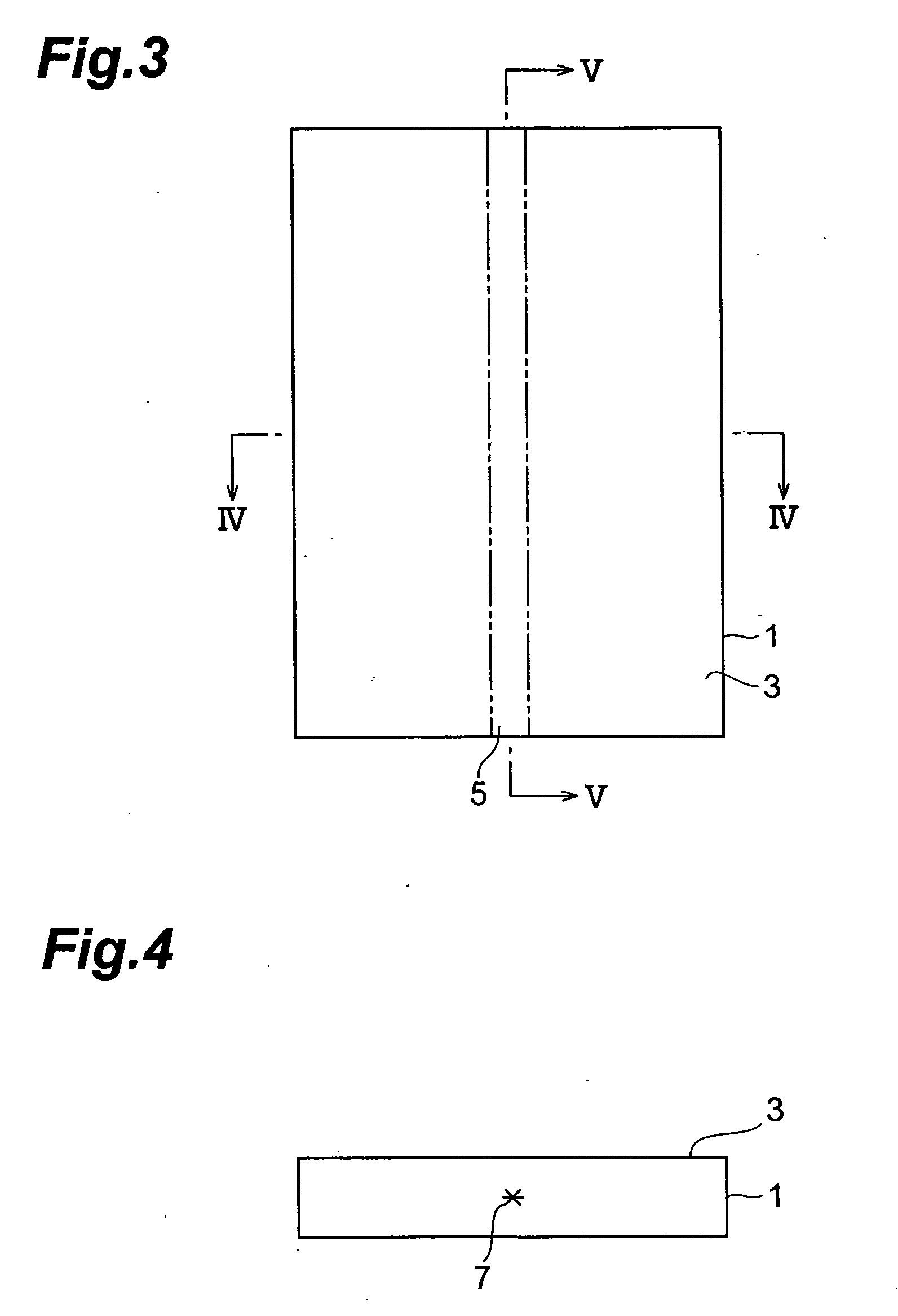
wafer-like (i.e., thin, flat) object to be processed, so as to form a modified region by multiphoton absorption within the object. When a stop member is disposed on an
optical path of laser light connecting the
beam expander and the first light-transmitting hole to each other, the amount of laser light cut by the surrounding part of the first light-transmitting hole can be made smaller than that in the case where the laser light having a beam size enlarged by the beam expander is directly emitted to the first light-transmitting hole of the lens holder, whereby the heating of the lens holder by the cut laser light can be suppressed. Also, even when the stop member is heated by the part of laser light cut by the surrounding part of the second light-transmitting hole, heat is prevented from being transmitted from the stop member to the lens holder, since the stop member is separated from the lens holder. Therefore, the positional fluctuation in light-converging point of laser light mainly due to the heating of the lens holder during laser processing can be suppressed to a low level, whereby the modified region can be formed accurately at a predetermined position within the wafer-like object to be processed.
[0008] When the laser light emitted from the beam expander is substantially parallel light, it will be preferred if the second light-transmitting hole has a
diameter not greater than that of the first light-transmitting hole. When the laser light emitted from the beam expander is completely parallel light, the diameter of laser light having passed the second light-transmitting hole of the stop member can be made equal to that of the first light-transmitting hole if the diameter of the second light-transmitting hole and that of the first light-transmitting hole are the same. When the laser light emitted from the beam expander is substantially parallel light but slightly expands, the laser light can hardly be incident on the surrounding part of the first light-transmitting hole if the diameter of the second light-transmitting hole is made smaller than that of the first light-transmitting hole in view of the expansion of the laser light. Hence, while allowing the condenser lens to exhibit its light-converging characteristic to the maximum, the amount of laser light cut by the surrounding part of the first light-transmitting hole can substantially be eliminated, whereby the heating of the lens holder can further be suppressed. Here, the substantially parallel light encompasses completely parallel light as well.
[0009] When the laser
light source emits the laser light at a
beam diameter φ0 and a
divergence angle 2θ0, and the beam expander enlarges the beam size of the laser light by a
magnification M and emits the laser light at a
divergence angle 2θ1; assuming that d1 is the distance between an exit part of the laser
light source and an entrance part of the beam expander, d2 is the distance between an exit part of the beam expander and an entrance opening of the second light-transmitting hole, and d3 is the distance between the entrance opening of the second light-transmitting hole and an entrance opening of the first light-transmitting hole; and letting φL be the diameter of the first light-transmitting hole, and φS be the diameter of the second light-transmitting hole; it will be preferred if φL and φS satisfy the relationship of ϕL{M(ϕ0+2d1tan θ0)+2d2tan θ1}M(ϕ0+2d1tan θ0)+2(d2+d3)tan θ1≥ϕs. When the laser light emitted from the beam expander is divergent light, the laser light can hardly be incident on the surrounding part of the first light-transmitting hole if the diameter φL of the first light-transmitting hole and the diameter φS of the second light-transmitting hole satisfy the above-mentioned relationship. Hence, the amount of laser light cut by the surrounding part of the first light-transmitting hole can substantially be eliminated, whereby the heating of the lens holder can further be suppressed.
[0010] When the laser
light source emits the laser light at a
beam diameter φ0 and a
divergence angle 2θ0, and the beam expander enlarges the beam size of the laser light by a
magnification M and emits the laser light at a convergence angle 2θ1; assuming that d1 is the distance between an exit part of the laser light source and an entrance part of the beam expander, d2 is the distance between an exit part of the beam expander and an entrance opening of the second light-transmitting hole, and d3 is the distance between the entrance opening of the second light-transmitting hole and an entrance opening of the first light-transmitting hole; and letting φL be the diameter of the first light-transmitting hole, and φL be the diameter of the second light-transmitting hole, it will be preferred if φL and φS satisfy the relationship of ϕL{M(ϕ0+2d1tan θ0)-2d2tan θ1}M(ϕ0+2d1tan θ0)-2(d2+d3)tan θ1≥ϕs. When the laser light emitted from the beam expander is convergent light, the laser light can hardly be incident on the surrounding part of the first light-transmitting hole if the diameter φL of the first light-transmitting hole and the diameter φS of the second light-transmitting hole satisfy the above-mentioned relationship. Hence, the amount of laser light cut by the surrounding part of the first light-transmitting hole can substantially be eliminated, whereby the heating of the lens holder can further be suppressed.

