
Scheduling retransmission in access networks

a technology of access network and retransmission delay, applied in data switching network, frequency-division multiplex, instruments, etc., can solve the problems of low utilization of transmission medium, unsatisfactory tcp slow start, excessive and highly undesirable load on this link, etc., and achieve the effect of reducing the delay of retransmission

Inactive Publication Date: 2009-02-10
VRINGO INFRASTRUCTURE
View PDF12 Cites 13 Cited by
  • Summary
  • Abstract
  • Description
  • Claims
  • Application Information

AI Technical Summary

Benefits of technology

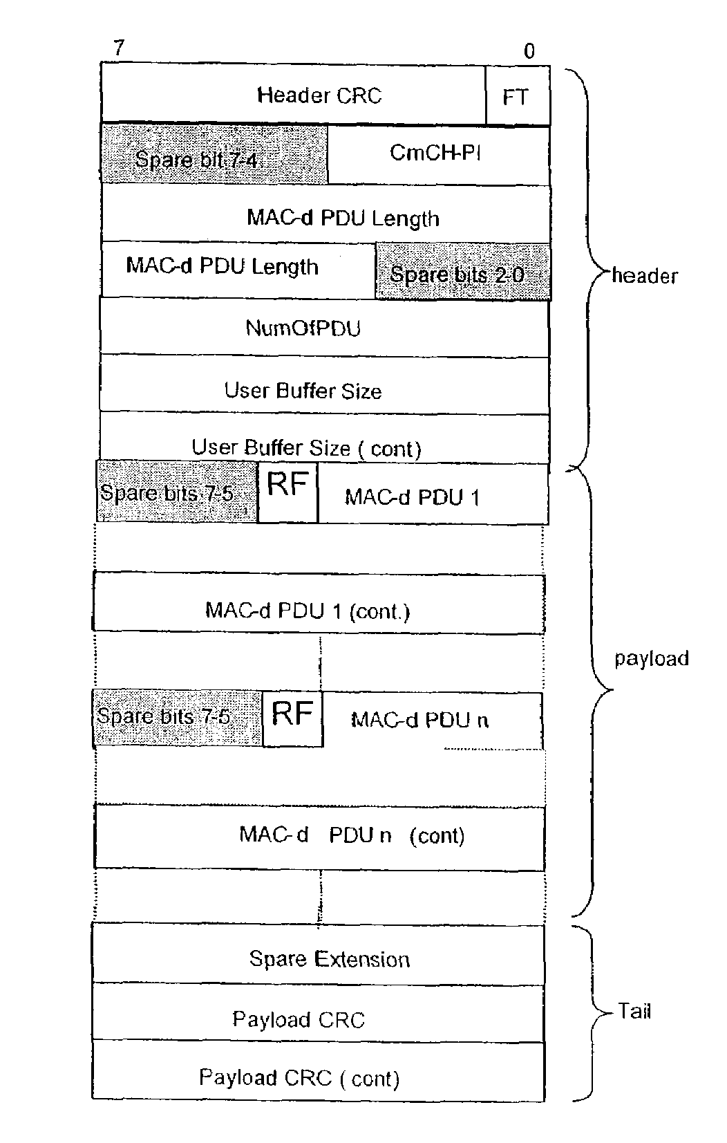
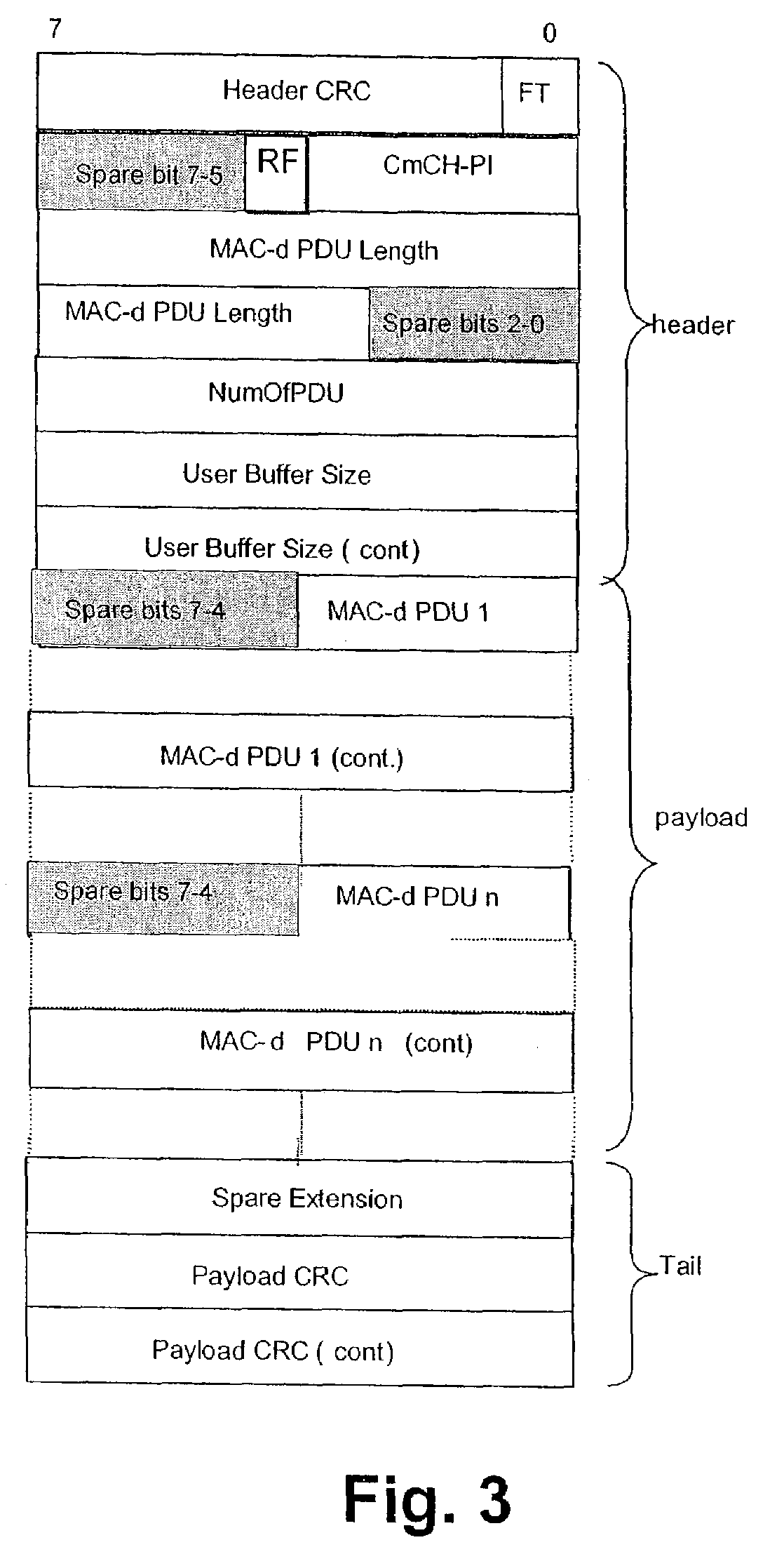
[0012]The present invention provides a scheduling scheme for access networks, by means of which retransmission delay can be decreased even with large buffer storage at the Node-B.
[0019]Accordingly, retransmitted data packets can be prioritized during scheduling to thereby reduce the retransmission delay and increase the throughput as seen by the application or user. Large buffer storages can thus be allowed for at the base station devices, while the risk of RLC stalling and TCP retransmission is minimized.

Problems solved by technology

However, the provision of such large buffers leads to the following problems:At some point, RLC PDUs, which are located in the Node-B may be retransmitted by an RLC retransmission from the RNC.
If there are always provided e.g. 3-4 times as much data as the average capacity stored in the Node-B in order to facilitate sufficient multi-user diversity, substantial data sent over the lub / lur interface has to be retransmitted, which leads to an excessive and highly undesirable load on this link.
TCP slow starts are undesirable since they lead to low utilization of the transmission medium.
From the above it can be understood that sudden very large delays for some blocks may lead to TCP timeouts.
The delay caused by a RLC retransmission is considerable, since the retransmission is put at the back of the queue in the Node-B.
Since RLC retransmissions only happen very seldom, the RTO algorithm cannot adjust to them.
Thus, an RLC retransmission creates a sudden delay increase which may be interpreted by TCP as congestion, leading to undesirable congestion actions.The RLC transmission is based on an RLC window.
This is called stalling and leads to a lower throughput for the user.

Method used


Image

  • Scheduling retransmission in access networks
  • Scheduling retransmission in access networks
  • Scheduling retransmission in access networks

Examples


Embodiment Construction

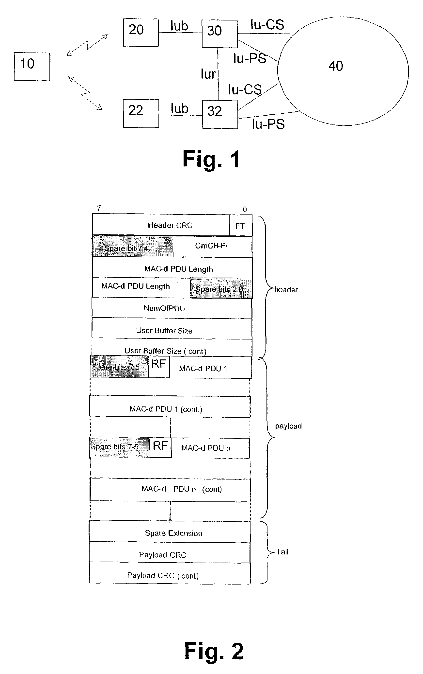
[0033]The embodiments of the present invention will now be described on the basis of a third generation WCDMA radio access network architecture as shown in FIG. 1.

[0034]FIG. 1 shows a terminal device or UE 10 connected via an air interface to a first Node-B 20 and / or a second Node-B 22. The first and second Node-Bs 20, 22 are connected via respective lub interfaces to first and second radio network controllers (RNCs) 30, 32 which are connected to each other via a lur interface. The Node-Bs 20, 22 are logical nodes responsible for radio transmission and reception in one or more cells to / from the UE 10 and terminate the lub interface towards the respective RNCs 30, 32. The RNCs 30, 32 are in charge of controlling use and integrity of radio resources within the radio access network. Furthermore, the RNCs 30, 32 provide connections to a third generation core network 40, e.g. a UMTS (Universal Mobile Telecommunications System) network for both circuit-switched traffic via a lu-CS interfa...


PUM


Abstract

The present invention relates to a method and system for scheduling data packets in a base station device of an access network. An information indicating a retransmission status of a data packet is provided to the base station device, and a scheduling priority is allocated to the data packet based on the retransmission status information. Thereby, retransmission packets can be scheduled earlier and round trip times can be reduced, so as to decrease the risk of timeouts and stalling and to loosen buffer requirements.

Description

BACKGROUND OF THE INVENTION[0001]1. Field of the Invention[0002]The present invention relates to a method and system for scheduling data packets in a base station device of an access network which provides access to a packet data network.[0003]2. Description of the Prior Art[0004]Within the International Telecommunications Union (ITU), several different air interfaces are defined for third generation mobile communication systems, based on either Code Division Multiple Access (CDMA) or Time Division Multiple Access (TDMA) technology. Wideband CDMA (WCDMA) is the main third generation air interface and will be deployed in Europe and Asia, including Japan and Korea, in the same frequency band, around 2 GHz.[0005]The WCDMA air interface has been defined to provide, in the first phase, data rates up to 2 Mbps in the 3GPP (third generation partnership project) Release 99 and Release 4 specifications. In the Release 5 specification, peak data rates up to 10 Mbps are possible with a High Sp...

Claims


Application Information

Patent Timeline
Patent Type & Authority Patents(United States)
IPC IPC(8): H04L12/56H04L1/16H04L1/18
CPCH04L1/16H04L1/1874H04L1/1887H04L12/5693H04L47/14H04L47/54H04W72/1242H04L1/1819H04W72/1284H04L47/50H04W72/569H04W72/21H04W8/04
Inventor WIGARD, JEROENKOLDING, TROELSMOGENSEN, PREBENAMEIGEIRAS, PABLOHWANG, WOONHEEHAKKINEN, HANNU
Owner VRINGO INFRASTRUCTURE
Learn More