

Tube scraper
a scraper and tube technology, applied in the field of scrapers, can solve the problems of reducing thermal efficiency and restricting fluid flow through the tubes, and achieve the effect of increasing the effectiveness of the scraper and increasing the scraper
- Summary
- Abstract
- Description
- Claims
- Application Information
AI Technical Summary
Benefits of technology
Problems solved by technology
Method used
Image

Examples
Embodiment Construction
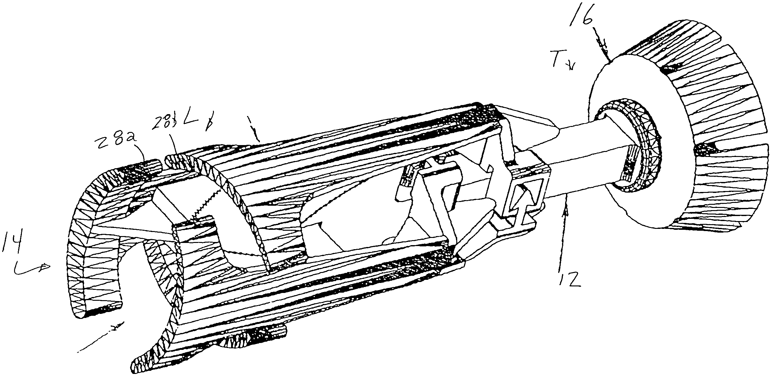
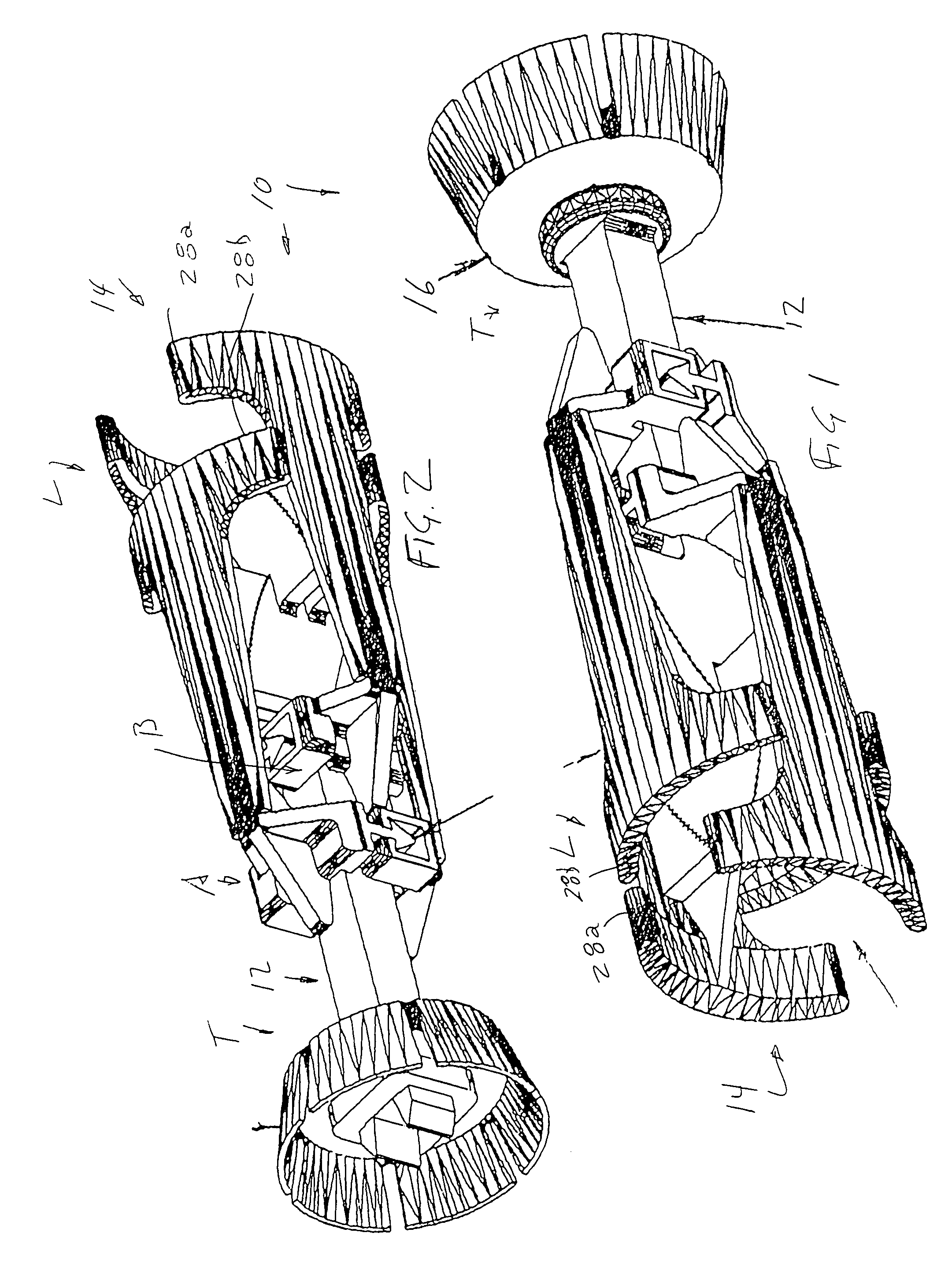
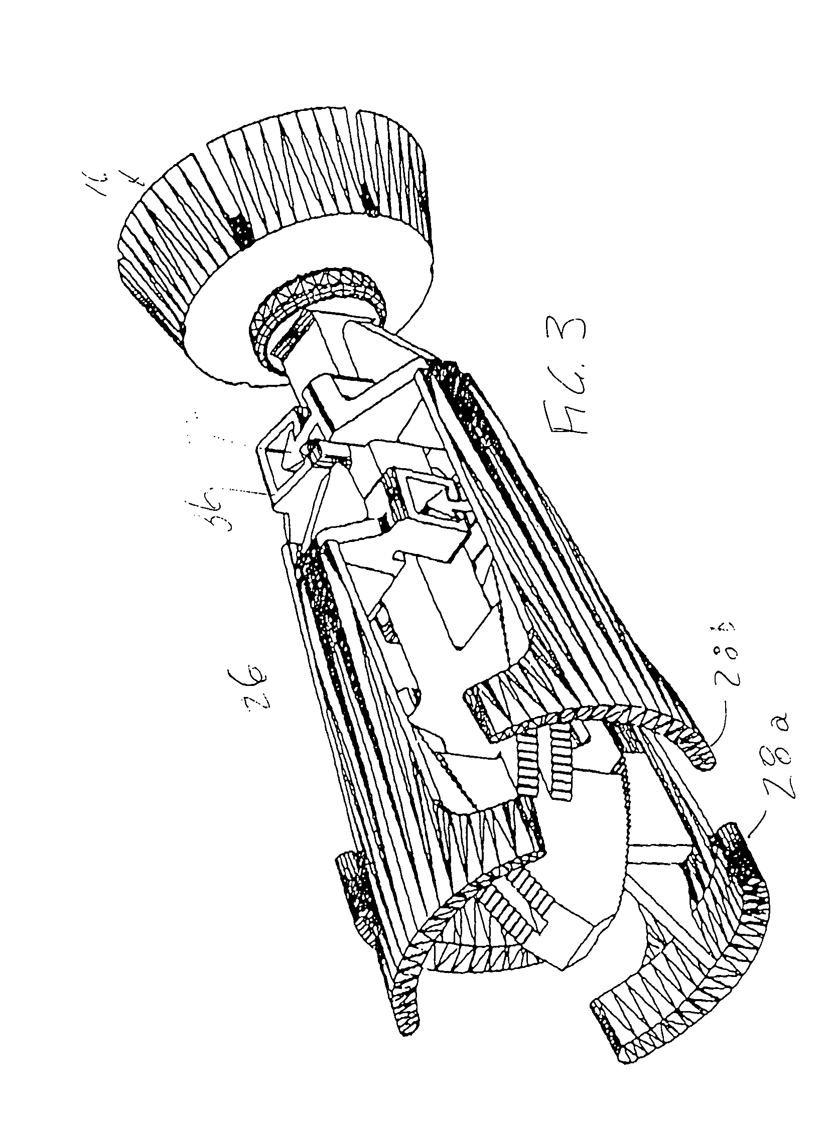
[0034]Referring to FIGS. 1-8 of the drawing, the present invention comprises a tube scraper 10 having an elongate arbor 12, set of scraper blade arms 14 and a piston 16 sealing the scraper against a tube wall for pneumatically or hydraulically propelling the scraper through the tube.
[0035]As shown in FIGS. 1-6 and 8 the arbor defines a longitudinal axis of the scraper. As best shown in FIG. 6, the arbor 12 includes a central beam 12a of rectangular, preferably square cross section on which a set of scraper blades is mounted. A thrust bearing 18 encircles the trailing end of the beam, and a set of spring fingers 20a-b extend rearward of the beam for mounting a propelling piston 16 (FIGS. 1-6). The piston and thrust bearing receive the pneumatic or hydraulic driving force applied to the scraper in cleaning a tube.
[0036]At its leading end the arbor has first 22 and second 24 inclined or converging ratcheting surfaces positioned about the arbor for the purpose of holding the set of scra...
PUM
 Abstract
Description
Claims
Application Information