Method of producing a rotary member made of a metallic plate

a technology of metallic plates and rotary members, which is applied in the direction of forging/hammering/hammering apparatus, forging/hammering/pressing machines, and forging equipment, etc. it can solve the problems of difficult to form such a boss having a predetermined diameter and a predetermined projecting height, or to form such a narrow annular space, etc., to reduce thickness, improve the dimensional precision of the resulting product, and prevent the effect of lowering the strength

Inactive Publication Date: 2009-02-17
KANEMITSU KK
View PDF7 Cites 17 Cited by
  • Summary
  • Abstract
  • Description
  • Claims
  • Application Information

AI Technical Summary

Benefits of technology

[0009]According to the method of producing a rotary member made of a metallic plate of the present invention, all the first curving step of curving a metallic blank for forming a case-like boss, the bending step of bending the resulting arcuate portion of the blank and the second curving step of pushing the flat portion to form a case-like peripheral wall, are a kind of bending operations. This restrains the blank from being reduced in thickness due to a plastic flow of the blank material, thus restraining the strength from being lowered. Further, even though the metallic blank is considerably thick, a predetermined boss and a pre-determined peripheral wall can be readily formed with the use of a relatively small-size press machine. Further, at the bending step, the outer peripheral edge portion of the blank is restrained from radially outwardly extending. This prevents the blank material from being outwardly moved, but causes the blank material to be moved toward the center of the blank. Accordingly, there can be formed a boss having a sufficient thickness and a predetermined projecting height, even though the boss has a small inner diameter. Further, at the second curving step, the boss formed at the bending step is restrained from being deformed. This prevents the blank material from being moved both inwardly and outwardly. Thus, the boss can be prevented from being deformed, and the peripheral wall having a sufficient thickness can be formed. Further, the outer peripheral edge of the blank is restrained from radially outwardly extending, and the boss is restrained from being deformed. This improves the dimensional precision of the resulting product in its entirety.
[0010]The method according to the present invention may further comprise, after the bending step, a finishing step of axially compressing the bottom of the case-like boss formed at the bending step such that the bottom becomes flat and is located at a predetermined projecting height. In such an arrangement, the boss having a predetermined projecting height can be finished with higher precision. Further, a boss portion which projects excessively in the height direction, can be axially compressed to cause the boss to be thickened. This is more advantageous in view of the strength of the boss.
[0011]The method according to the present invention may further comprise, after the second curving step, a cutting step of cutting the projecting end portion of the case-like boss having the bottom formed at the bending step, thus forming a shaft insertion hole in the case-like boss. In such an arrangement, even though there occur errors about dimensional precision at the curving and / or bending steps, such errors can be absorbed, thus ultimately providing a rotary member of which dimensional precision is very high.

Problems solved by technology

When producing such a sheet metal product from a thick blank in order to assure a sufficient strength, it is difficult to form such a boss having a predetermined diameter and a predetermined projecting height, or to form such a narrow annular space, even though there is used a large-size press machine of the class of 2,000 tons to 2,500 tons.

Method used


Image

  • Method of producing a rotary member made of a metallic plate
  • Method of producing a rotary member made of a metallic plate
  • Method of producing a rotary member made of a metallic plate

Examples


Embodiment Construction

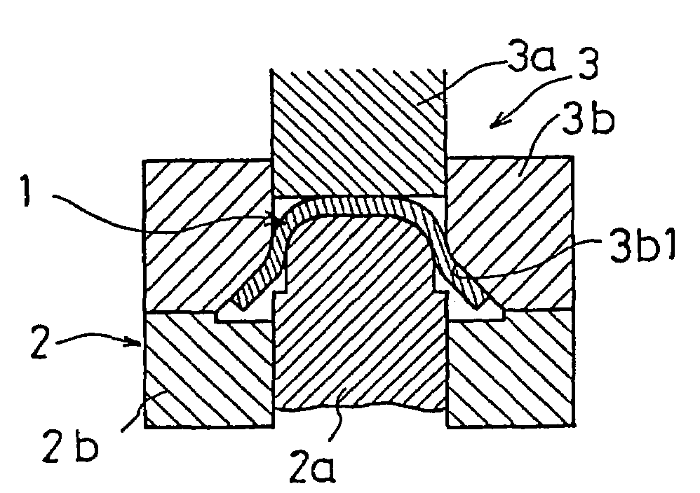
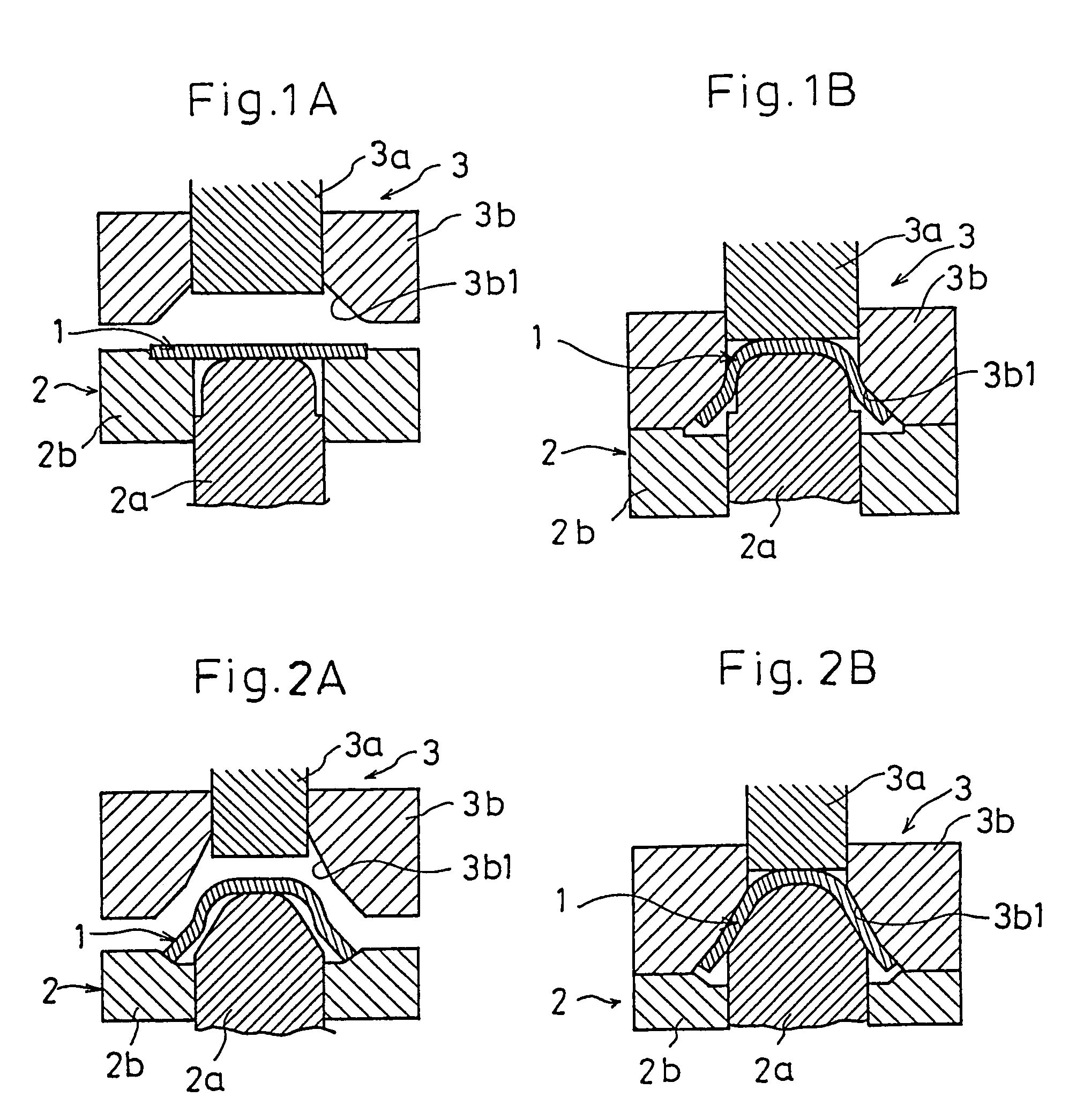
[0023]The following description will discuss a method of producing a rotary member made of a metallic plate according to an embodiment of the present invention, in the form of a method of producing a rotor to be used as assembled in an electromagnetic clutch. In this embodiment, using a circular plate-like metallic blank having a thickness t of about 3 to about 5, there is formed a rotor for an electromagnetic clutch having (i) a boss of which inner diameter d1 is about 60 mm and of which projecting height h is in the range from about 28 to about 32 mm, and (ii) a peripheral wall of which outer diameter d2 is in the range from about 120 to about 150 mm.

[0024]FIG. 1A shows a first sub-step of a first curving (drawing) step. As shown in FIG. 1A, a circular flat metallic blank 1 is set on a lower mold 2 having a punch 2a and a punch holder 2b, and a press machine (not shown) is operated such that the lower mold 2 and an upper mold 3 having a die 3a and a die holder 3b approach to each ...


PUM

PropertyMeasurementUnit
outer diameter d2aaaaaaaaaa
heightaaaaaaaaaa
heightaaaaaaaaaa

Abstract

The method according to the present invention comprises: a first curving step of curving a plate-like metallic blank (1) such that the blank (1) is convexed; a bending step of bending, with the outer peripheral edge portion (1e) of the blank (1) restrained from radially outwardly extending, the resulting arcuate portion (1b) of the curved blank (1) in the direction opposite to the convex direction thereof, so that a boss (6) is formed; and a second curving step of pushing the inner peripheral portion of a flat portion (5) of the blank (1) in the direction opposite to the boss projecting direction. Through the steps above-mentioned, the blank (1) is provided at the center thereof with the case-like boss (6) projecting in one direction from one lateral side of the blank (1) and at the outer periphery thereof with a peripheral wall (7) projecting in the same direction in which the boss (6) projects. Thus, with a small press machine, there can be securely formed, with high precision, a boss having a desired diameter and a desired projecting height, without the original thickness of the blank (1) decreased so much in the course of production steps.

Description

[0001]This patent application is a continuation of U.S. patent application Ser. No. 08 / 841,108, filed Apr. 30, 1997, now abandoned, which is a further continuation of U.S. patent application Ser. No. 08 / 146,005, filed Nov. 4, 1993, now abandoned, which is a national stage entry of PCT / JP92 / 00508 filed Apr. 20, 1992.TECHNICAL FIELD[0002]The present invention relates to a method of producing a rotary member made of a metallic plate to be used as an inner wheel of a V-pulley, a rotor of an electromagnetic clutch or the like, such a rotary member being obtained by (i) integrally forming, at the center of a plate-like metallic blank, a case-like boss adapted to be put on a rotary body such as a rotary shaft, the case-like boss projecting in one direction from one lateral side of the blank, and (ii) integrally forming, at the outer periphery of the plate-like metallic blank, a case-like peripheral wall concentrically projecting in the same direction in which the boss projects. Also, the p...

Claims


Application Information

Patent Timeline
Patent Type & Authority Patents(United States)
IPC IPC(8): B21D22/30B21D53/26B21D53/18F16C13/00F16H55/00
CPCB21D53/18B21D53/261
Inventor KANEMITSU, TOSHIAKIODA, KAZUYUKI
Owner KANEMITSU KK
Why Eureka
Try Eureka