
Dual cylinder lift pump and method of recovering fluids from subsurface formations

a technology of lift pump and subsurface formation, which is applied in the direction of positive displacement liquid engine, sealing/packing, borehole/well accessories, etc., can solve the problem of extreme low horsepower requirements and achieve the effect of lowering horsepower requirements

Active Publication Date: 2009-02-17
BRECHEISEN MARION
View PDF6 Cites 7 Cited by
  • Summary
  • Abstract
  • Description
  • Claims
  • Application Information

AI Technical Summary

Benefits of technology

This solution results in a more energy-efficient, low-maintenance pumping system with reduced power requirements, enabling continuous operation without interfering with other ground-level activities, and allowing for remote control and monitoring capabilities.

Problems solved by technology

Utilization of the counterbalanced cylinders results in extremely low horsepower requirements.

Method used


Image

  • Dual cylinder lift pump and method of recovering fluids from subsurface formations
  • Dual cylinder lift pump and method of recovering fluids from subsurface formations
  • Dual cylinder lift pump and method of recovering fluids from subsurface formations

Examples


Embodiment Construction

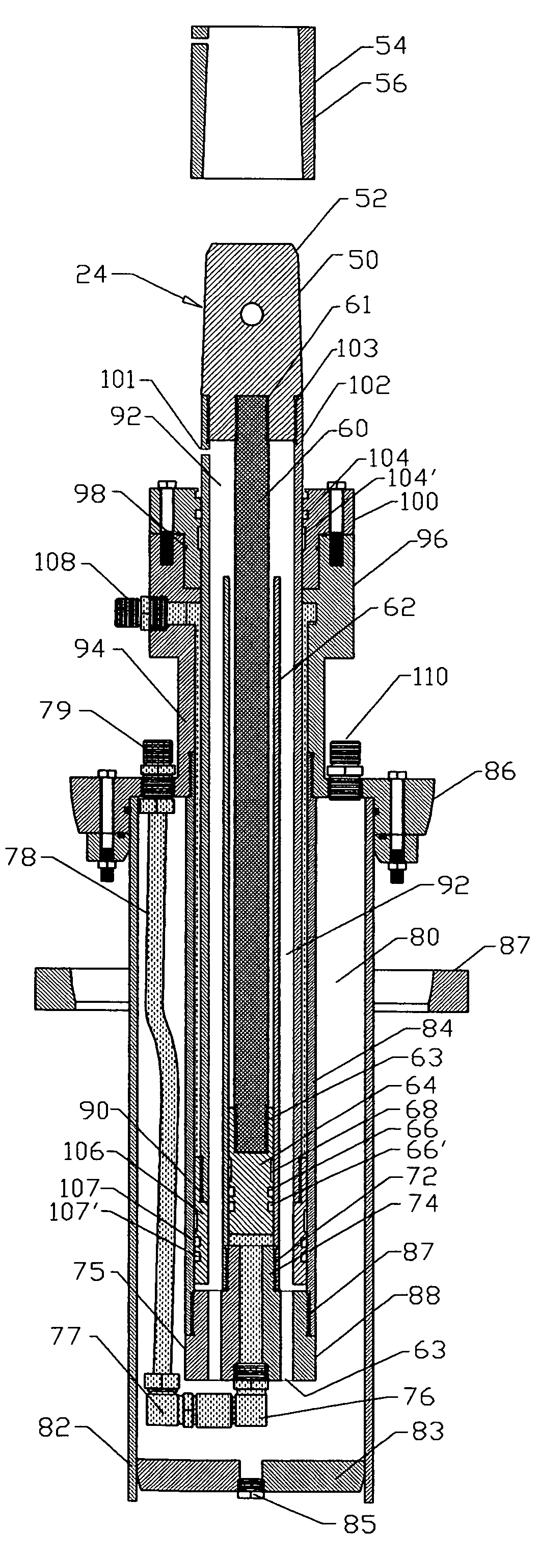
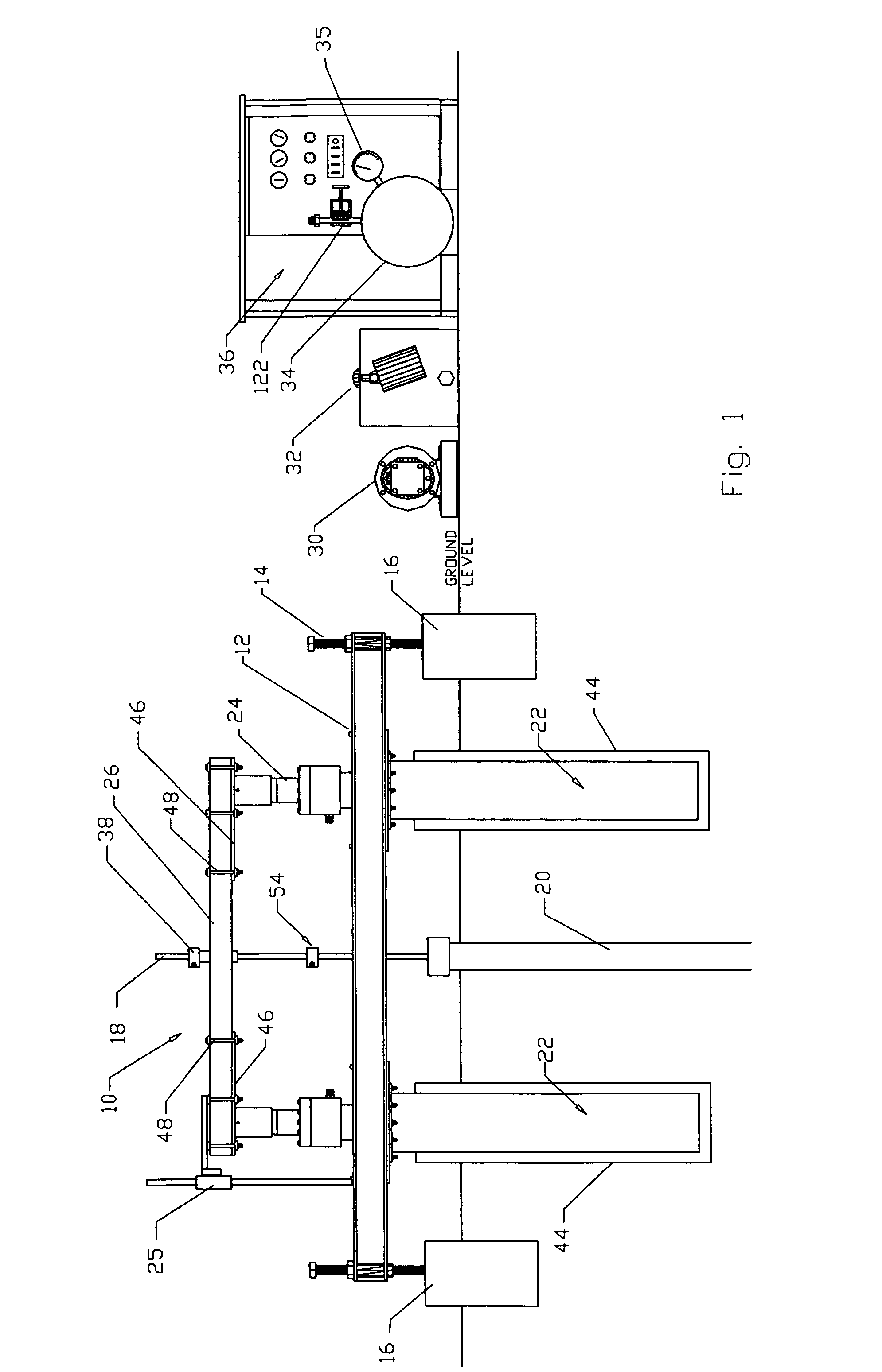
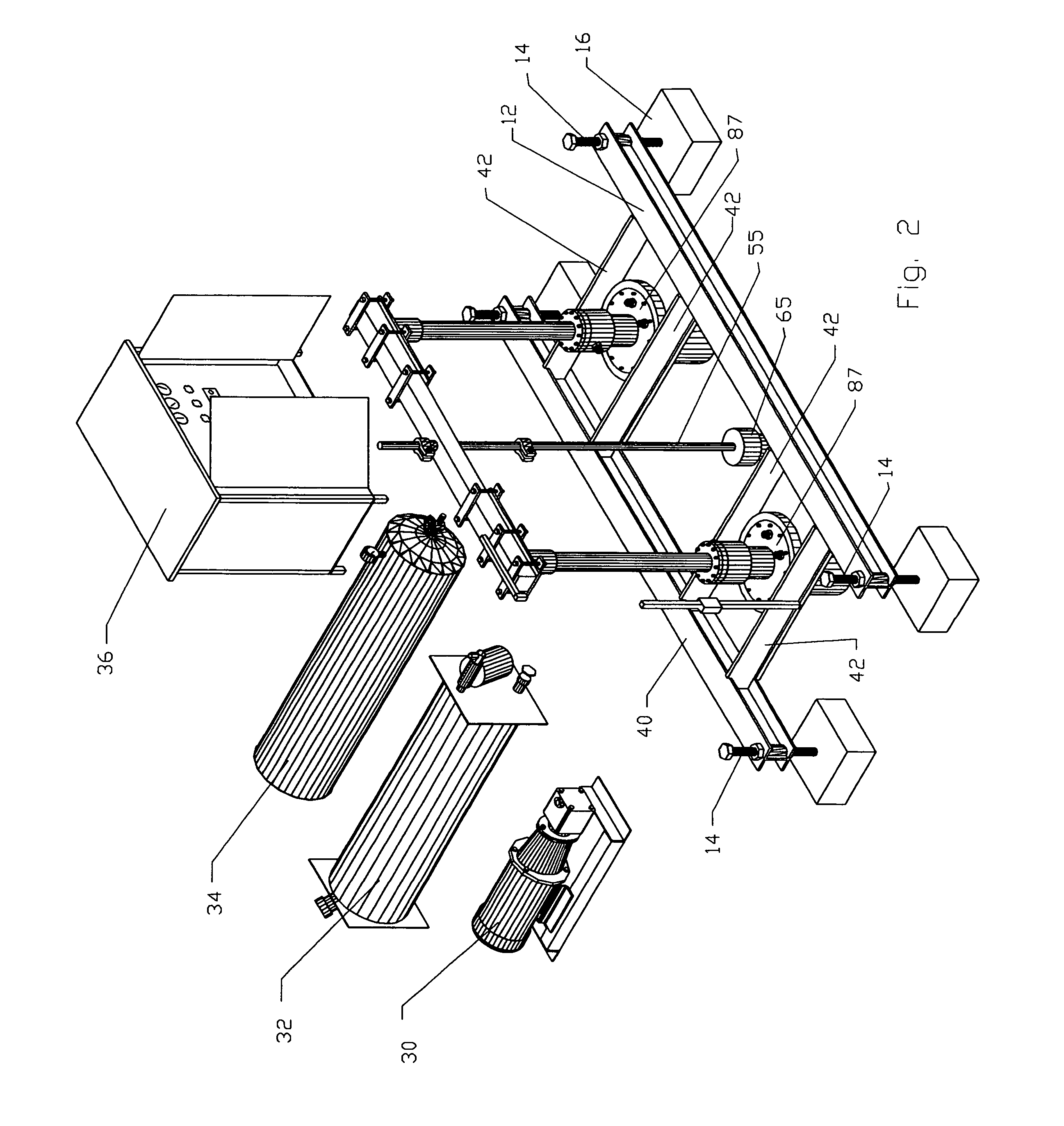
[0019]Referring in detail to the drawings, there is shown by way of illustrative example in FIGS. 1 and 2 a pump jack system 10 for the extraction of oil and gas from subsurface formations which is broadly comprised of a base frame or platform 12 adjustably mounted by leveling screws 14 in concrete footings 16; and a conventional pump rod extends downwardly through an existing well casing 20 and is flanked on opposite sides by cylinder assemblies 22, each assembly 22 having a piston 24 mounted at its upper end to a cross bar 26. In the embodiment shown in FIGS. 1 to 4, a combination of hydraulic fluid and nitrogen gas are supplied to each cylinder 22 in a manner to be described from a hydraulic motor 30 connected to a reservoir 32 and a nitrogen supply 34. A suitable control panel 36 regulates the supply of hydraulic fluid to the cylinders 22 to control lifting and lowering of the pump rod via the cross bar 26 and pump rod clamps 38 which are adjustably mounted on the upper end of t...


PUM


Abstract

A pump jack system for reciprocating a pump rod string is made up of a base frame and piston drive cylinders mounted on the base frame with the upper end of the pump rod connected to the cylinder assemblies, the cylinder assemblies being operated in unison by a fluid control circuit communicating with inner and outer concentric fluid passages, and the pump rod string is counterbalanced by a fluid circuit which supplies pressure in an upward direction to each of the pistons on each upstroke and substantially reduces the pressure on each downstroke, the fluid circuit being selected from an inert gas alone or an inert gas pressurizing a hydraulic fluid.

Description

BACKGROUND AND FIELD[0001]This invention relates to down-hole pumping systems and more particularly relates to a low profile pump jack system and method of extracting fluids, such as, oil and gas from subsurface formations.[0002]A wide variety of pumping devices have been developed over the years for extracting fluids from wells drilled into subsurface formations. One well-known device, commonly referred to as a “walking beam pump” is characterized by having a sucker rod string attached to one end of the beam, the beam being driven by a motive drive source, such as, a motor coupled to the opposite end of the beam by a pitman arm. Typically, the sucker rod will extend for considerable distances into the well and is connected to a down-hole pump, and in response to rocking motion of the walking beam initiated by the prime mover through the pitman arm is raised and lowered to result in drawing of the fluid out of the well.[0003]The rocking motion of the walking beam will counterbalance...

Claims


Application Information

Patent Timeline
Patent Type & Authority Patents(United States)
IPC IPC(8): E21B34/10
CPCE21B43/126E21B43/129
Inventor BRECHEISEN, MARION
Owner BRECHEISEN MARION
Learn More