
Light emitting apparatus, backlight apparatus, and electronic apparatus

a technology of backlight apparatus and light source, which is applied in the direction of light source for lighting systems, planar/plate-like light guides, lighting and heating apparatus, etc., can solve problems such as contributing to the improvement of radiation angle, and achieve high coupling efficiency

Active Publication Date: 2009-02-17
LEDCOMM LLC
View PDF4 Cites 20 Cited by
  • Summary
  • Abstract
  • Description
  • Claims
  • Application Information

AI Technical Summary

Benefits of technology

"The present invention provides a thin and small light emitting apparatus with a high coupling efficiency with a light guide plate. The apparatus includes a placement surface with an electrode, a light emitter placed on the surface, and a transparent sealing resin that seals the light emitter and forms a concave surface facing the light emitter, from which light outgoes. The concave surface has a depth that is equal to or deeper than a half of its width in a short-axis direction. This structure reduces the radiation angle and increases the luminous intensity in an axial direction, making it highly efficient in coupling with the light guide plate of a liquid crystal display apparatus. The invention also provides a backlight apparatus and an electronic apparatus including the light emitting apparatus."

Problems solved by technology

This, however, occurs naturally as a result that the diffusion agent absorbs a part of component of the sealing resin during the thermal curing, and therefore does not contribute to improvement in the radiation angle, in a short-axis direction, of the package.

Method used


Image

  • Light emitting apparatus, backlight apparatus, and electronic apparatus
  • Light emitting apparatus, backlight apparatus, and electronic apparatus
  • Light emitting apparatus, backlight apparatus, and electronic apparatus

Examples


Embodiment Construction

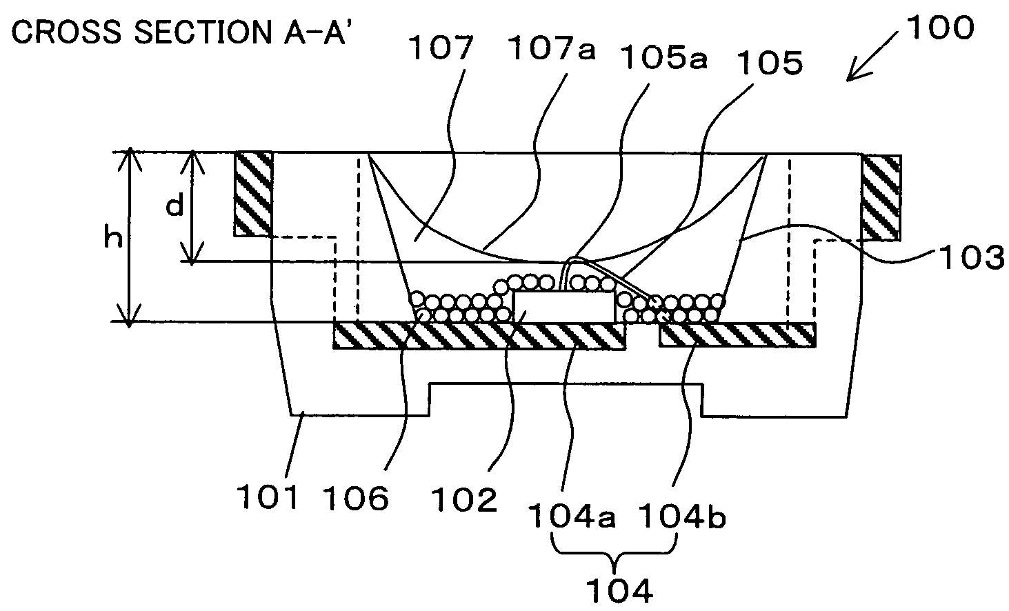
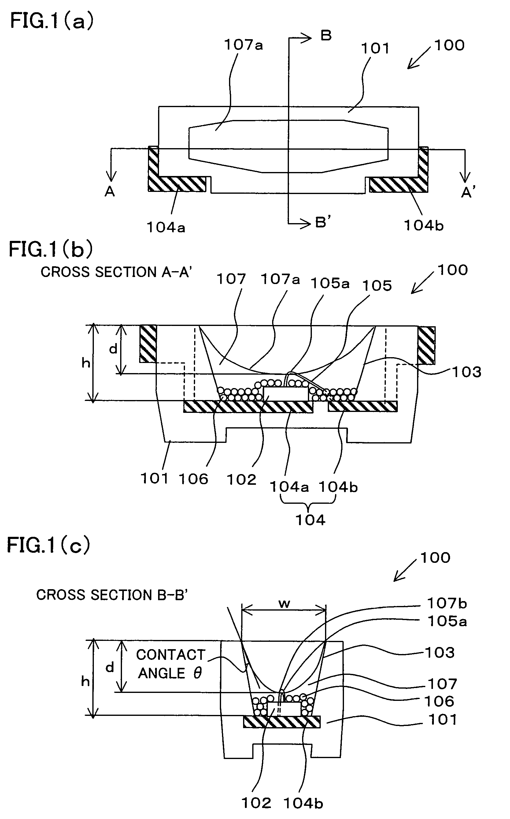
[0031]The following explains an embodiment of a light emitting apparatus according to the present embodiment, with reference to figures. FIG. 1(a) is a diagram showing a light emitting apparatus 100 of the present embodiment, taken from a light-outgoing surface of the light emitting apparatus 100. FIG. 1(b) is a cross sectional diagram (A-A′) of the light emitting apparatus 100 in a long-axis direction.

[0032]The light emitting apparatus 100 includes: a package 101 that is substantially rectangular parallelepiped, is in bowl-shape, and includes a recess section having a depth of h; and a chip 102 that includes an electrode provided on its top surface that is a light-emitting surface. The recess section forms a reflector 103 that is constituted of a bottom surface (placement surface) and a tilted surface that extends from and along a periphery of the bottom surface. The reflector 103, as described below, may have a function of reflector that is realized by reflectivity of the package ...


PUM


Abstract

A light emitting apparatus according to the present invention includes: a placement surface that includes an electrode; a light emitter that is placed on the placement surface; and a transparent sealing resin that seals the light emitter, and forms a concave surface that is a light-outgoing surface via which light outgoes. The concave surface faces a surface of the light emitter, from which surface light is emitted. The light emitter and the electrode are connected via a wire that is curved in such a way that a top section of the curved wire substantially coincides with a deepest section of the concave surface.

Description

[0001]This Nonprovisional application claims priority under 35 U.S.C. § 119(a) on Patent Application No. 363886 / 2005 filed in Japan on Dec. 16, 2005, the entire contents of which are hereby incorporated by reference.FIELD OF THE INVENTION[0002]The present invention relates to a light emitting apparatus that includes a light emitter, and a package member that accommodates the light emitter and includes a recess section having a reflector function to cause light to outgo to the outside.BACKGROUND OF THE INVENTION[0003]An exemplary thin and plane light-source employed in a liquid crystal display apparatus and the like is shown in FIG. 6(c). Specifically, a light guiding plate 213 is provided on a rear surface of a liquid crystal display member 212, and a surface-mount type light emitting apparatus 200 is provided on a side surface of the light guiding plate 213. In the plane light-source, the light guiding plate 213 and the light emitting apparatus 200 are placed, adjacent to each othe...

Claims


Application Information

Patent Timeline
Patent Type & Authority Patents(United States)
IPC IPC(8): F21V7/00H01L33/32H01L33/50H01L33/56H01L33/60H01L33/62
CPCG02B6/003H01L33/54H01L33/486H01L2224/48091H01L2224/48247H01L2924/00014
Inventor TSUDA, YOICHI
Owner LEDCOMM LLC
Learn More