Dynamic phase alignment for resynchronization of captured data

a technology of dynamic phase alignment and captured data, applied in the field of memory controllers, can solve the problems of resynchronizing captured data, variable delay, time delay can vary from one device to another, etc., and achieve the effect of optimal resynchronization

Inactive Publication Date: 2009-02-17
ALTERA CORP
View PDF10 Cites 16 Cited by
  • Summary
  • Abstract
  • Description
  • Claims
  • Application Information

AI Technical Summary

Benefits of technology

[0013]In accordance with the present invention, test data is written to the external memory device, and is then read back several times. Attempts are made to resynchronize the captured data with the system clock, with relative variations in the phase of the captured data and the system clock, in order to select a value for the relative phase, which allows for optimum resynchronization.

Problems solved by technology

However, there then remains the problem of resynchronizing the captured data with the clock signal which controls the other components of the electronic device.
This can be difficult because, although the clock signal accompanying the returned data is derived originally from the system clock, it is offset by a variable delay.
In addition, even in devices which have been manufactured to the same specification, the time delay can vary from one device to another, because of manufacturing process variations.
Further, the time delay can vary in use of a single device, because of changes in the supply voltage and / or the operating temperature of the device.
The problem of resynchronization of the captured data with the system clock is particularly acute in the case of high speed memory devices, such as DDR (Double Data Rate) memory devices, and similar memory devices.
However, it is time consuming to perform this analysis.
Further, changes in the time delay resulting from changes in the operating voltage and temperature cannot be compensated in this way.

Method used


Image

  • Dynamic phase alignment for resynchronization of captured data
  • Dynamic phase alignment for resynchronization of captured data
  • Dynamic phase alignment for resynchronization of captured data

Examples


first embodiment

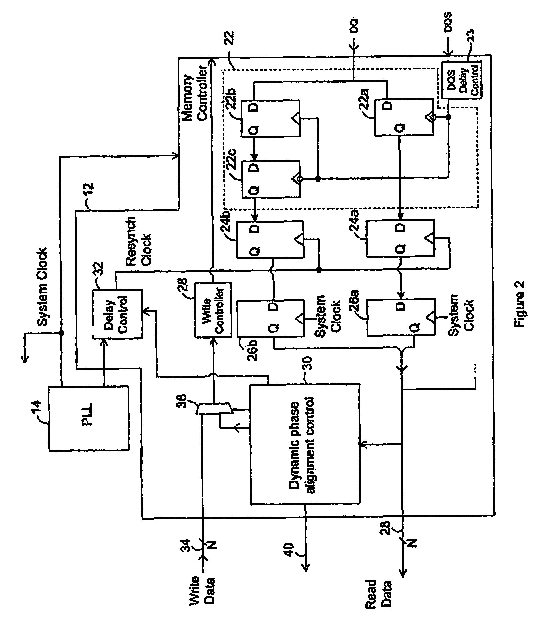
[0026]FIG. 2 is a block schematic diagram of a memory controller, in accordance with the present invention.

[0027]As is generally conventional, the memory controller 12 includes a capture register block 22. More specifically, the memory controller 12 is connected to the external memory device 6 by way of a connector which may, for example, be 64 bits wide. In that case, where the external memory device is a DDR device, or a similar device as described above, there is a capture register block 22 for each pair of data bits, although FIG. 2 shows only one capture register block in detail for ease of illustration. Again, as is conventional, the capture register block 22 includes a first capture register 22a, a second capture register 22b, and a third capture register 22c.

[0028]The received data signal DQ is passed to the first and second capture registers 22a, 22b, and the output of the second capture register 22b is passed to a third capture register 22c. The second capture register 22...

second embodiment

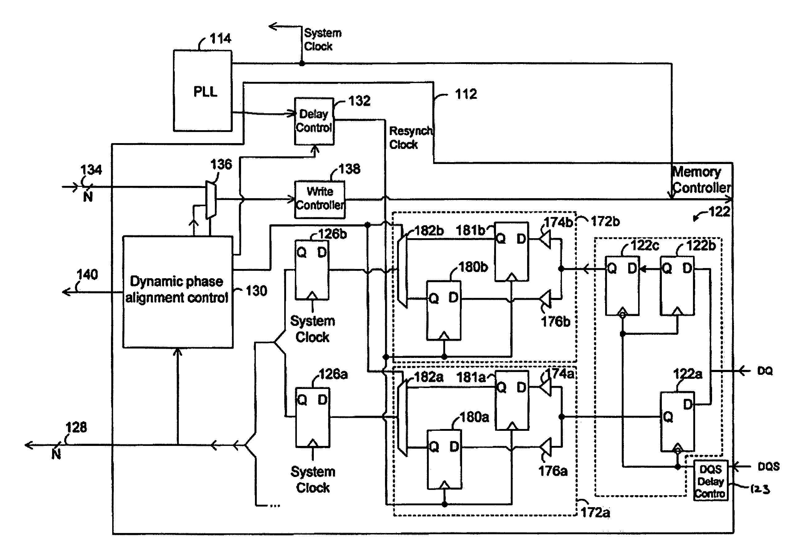
[0054]Thus, FIG. 5 is a block schematic diagram of a memory controller 112, in accordance with the present invention. As is generally conventional, the memory controller 112 includes capture register blocks 122. More specifically, the memory controller 112 is connected to the external memory device 6 by way of a connector which may, for example, be 64 bits wide. In that case, where the external memory device is a DDR device, or a similar device as described above, there is a capture register block 122 for each pair of data bits, although FIG. 5 shows only one capture register block in detail for ease of illustration. Again, as is conventional, the capture register block 122 includes a first capture register 122a, a second capture register 122b, and a third capture register 122c.

[0055]Again, as is conventional, the received data signal DQ is passed to the first and second capture registers 122a, 122b, and the output of the second capture register 122b is passed to a third capture re...


PUM


Abstract

A source synchronous external memory device returns data to a memory controller of an electronic device with its own clock signal, which allows the returned data to be captured with a high degree of accuracy. The captured data must then be resynchronized with the clock signal which controls the other components of the electronic device. This problem is particularly acute in the case of high speed memory devices, such as DDR (Double Data Rate) memory devices, and similar memory devices. Test data is written to the external memory device, and is then read back several times. Attempts are made to resynchronize the captured data with the system clock, with different relative variations in the phase of the captured data and the system clock, in order to select a value for the relative phase, which allows for optimum resynchronization.

Description

CROSS-REFERENCES TO RELATED APPLICATIONS[0001]Not ApplicableSTATEMENT AS TO RIGHTS TO INVENTIONS MADE UNDER FEDERALLY SPONSORED RESEARCH OR DEVELOPMENT[0002]Not ApplicableREFERENCE TO A “SEQUENCE LISTING,” A TABLE, OR A COMPUTER PROGRAM LISTING APPENDIX SUBMITTED ON A COMPACT DISK.[0003]Not ApplicableBACKGROUND OF THE INVENTION[0004]1. Technical Field of the Invention[0005]This invention relates to a memory controller, and to a method for use in a memory controller, in order to synchronize captured data with a system clock signal.[0006]2. Background of the Invention[0007]In many electronic devices, it is common for a separate memory device to be provided. Data must then be written to, and read from, this separate memory device, by way of a memory interface.[0008]A source synchronous external memory device returns data with its own clock signal, which allows the returned data to be captured with a high degree of accuracy. However, there then remains the problem of resynchronizing the...

Claims


Application Information

Patent Timeline
Patent Type & Authority Patents(United States)
IPC IPC(8): G06F13/00G06F1/12H03K19/00G06F12/00
CPCG11C29/02G11C29/022G11C29/023G11C29/028
Inventor THORNE, NEIL
Owner ALTERA CORP
Why Eureka
Try Eureka