Small gauge pressure sensor using wafer bonding and electrochemical etch stopping

a pressure sensor and wafer bonding technology, applied in the field of gauge pressure sensors, can solve the problem of pressure sensor to supply inaccurate read-out of pressure as measured by the pressure sensor

Active Publication Date: 2009-02-24
HONEYWELL INT INC
View PDF6 Cites 74 Cited by
  • Summary
  • Abstract
  • Description
  • Claims
  • Application Information

AI Technical Summary

Benefits of technology

[0010]The aforementioned aspects and other objectives and advantages can now be achieved as described herein. A gauge pressure sensor apparatus and method of forming the same are described herein. In general, such a pressure sensor can be configured by etching a constraint wafer partially to set the diaphragm size followed by bonding to a top wafer. The thickness of the top wafer is either the desired diaphragm thickness or is thinned to the desired thickness after bonding. Elements such as piezoresistive or capacitive elements can then be fabricated on the top diaphragm wafer before the final etching is accomplished in order to open a conduit for the pressure media. The wafer bonding of the top wafer and the constraint wafer enables electrochemical etch stopping to be utilized for determining when the final etching is completed. Such a configuration and process prevents the diaphragm from being etched. Additionally, this allows the die size to be smaller than die where the diaphragm size can be set by etching from the back side.

Problems solved by technology

Dirt or debris from processing steps can enter the cavity and remain within the cavity, interfering with the diaphragm as it deflects, which causes the pressure sensor to supply inaccurate read-out of the pressure as measured by the pressure sensor.
The challenge in this final etch step is to ensure the integrity of the thin diaphragm and the cavity walls supporting the thin diaphragm.

Method used


Image

  • Small gauge pressure sensor using wafer bonding and electrochemical etch stopping
  • Small gauge pressure sensor using wafer bonding and electrochemical etch stopping
  • Small gauge pressure sensor using wafer bonding and electrochemical etch stopping

Examples


Embodiment Construction

[0015]The particular values and configurations discussed in these non-limiting examples can be varied and are cited merely to illustrate at least one embodiment and are not intended to limit the scope thereof.

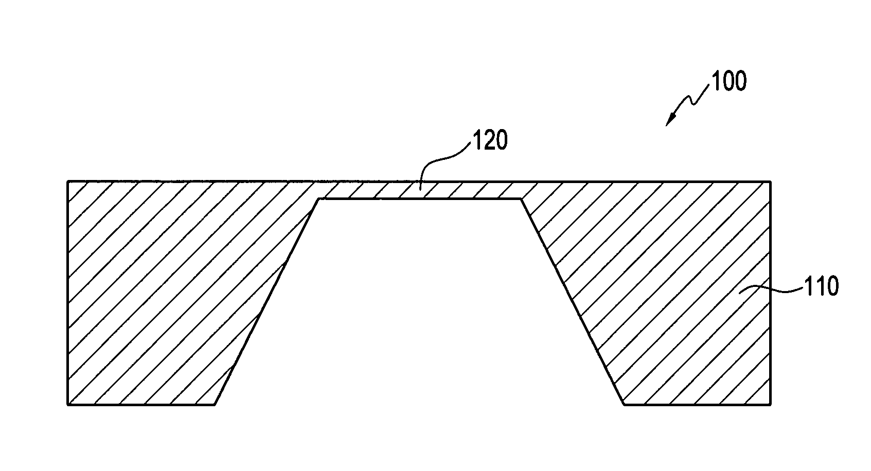
[0016]FIG. 1, illustrates a prior art micro-machined gauge pressure sensor 100. In the prior art apparatus 100 depicted in FIG. 1, an anisotropic back etch processes can be utilized to etch a single wafer 100 and expose a thin silicon diaphragm 120 supported over a silicon frame 110. The wafer 100 is subsequently etched from the backside to form the thin diaphragm 120 upon which piezoresistors can be formed utilizing implantation and diffusion techniques. Here, however, the die size is substantially greater than the minimum desired geometrical dimensions.

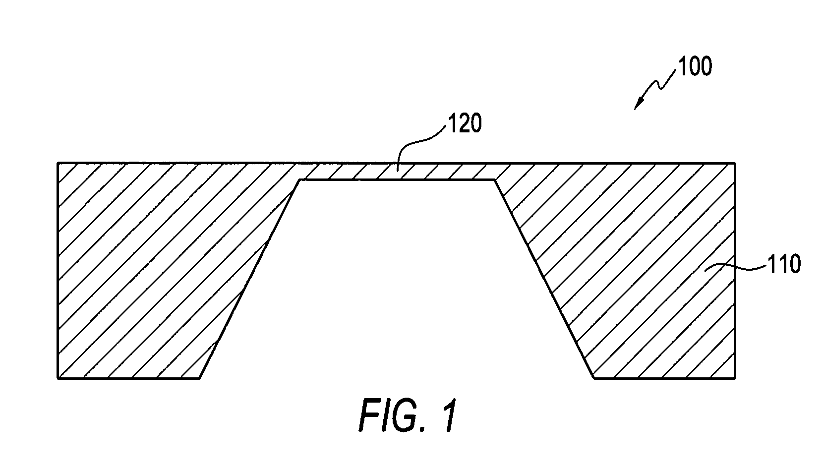
[0017]FIGS. 2-5 illustrates a simplified process flow for configuring a silicon gauge pressure sensor 200 in accordance with a preferred embodiment; Silicon gauge pressure sensor 200 can be fabricated by utilizing a P-type subs...


PUM

PropertyMeasurementUnit
lengthaaaaaaaaaa
sizeaaaaaaaaaa
thicknessaaaaaaaaaa

Abstract

A gauge pressure sensor apparatus and a method of forming the same. A constraint wafer can be partially etched to set the diaphragm size, followed by bonding to a top wafer. The thickness of the top wafer is either the desired diaphragm thickness or is thinned to the desired thickness after bonding. The bonding of top wafer and constraint wafer enables electrochemical etch stopping. This allows the media conduit to be etched through the back of the constraint wafer and an electrical signal produced when the etching reaches the diaphragm. The process prevents the diaphragm from being over-etched. The invention allows the die size to be smaller than die where the diaphragm size is set by etching from the back side.

Description

TECHNICAL FIELD[0001]Embodiments are generally related to gauge pressure sensors. Embodiments are also related to techniques for configuring gauge pressure sensors utilizing bonding and electrochemical etch stopping.BACKGROUND OF THE INVENTION[0002]Micromachined pressure sensors are widely incorporated into diverse equipment such as medical, laboratory, and industrial equipment and automotive circuitry. Smaller, more accurate pressure sensors are required for a new generation of equipment in the medical, analytical, and industrial fields while the cost of such pressure sensors must remain low in order to achieve advances at competitive prices.[0003]Typical micromachined pressure sensors can be configured by forming a cavity on the back side of a silicon wafer. Silicon gauge pressure sensors created using semiconductor processes can be made smaller in size by bonding two wafers together. New and novel approaches utilize two wafers bonded together to create a diaphragm. In this approa...

Claims


Application Information

Patent Timeline
Patent Type & Authority Patents(United States)
IPC IPC(8): G01L9/06
CPCG01L9/0042G01L9/0054
Inventor STEWART, CARL E.MORALES, GILBERTODAVIS, RICHARD A.
Owner HONEYWELL INT INC
Why Eureka
Try Eureka