Drive train

a technology of drive train and drive shaft, which is applied in the direction of mechanical actuated clutches, interlocking clutches, transportation and packaging, etc., can solve the problems of wear and loss of comfort, complex and expensive design of the clutch assembly, etc., and achieve the effect of simplifying the design, improving the operation, and cost-effective manufacturing

Active Publication Date: 2009-02-24
SCHAEFFLER TECH AG & CO KG
View PDF18 Cites 13 Cited by
  • Summary
  • Abstract
  • Description
  • Claims
  • Application Information

AI Technical Summary

Benefits of technology

[0004]An object of the present invention is to devise a drive train of the type mentioned at the outset in a way that will improve its operation and simplify its design, and ensure a cost-effective manufacturing. In addition or alternatively, the operation of the drive train according to the present invention should be especially simple, thereby enabling the use of an economically priced actuating system. It is also additionally or alternatively intended, by the special form and mode of operation of a clutch assembly designed in accordance with the present invention, to improve or optimize its installation between the engine and transmission, and / or to isolate the axial vibrations and wobble originating in the engine.
[0005]The present invention provides that the clutch assembly of the drive train is not only accommodated at the crankshaft itself, but also at the transmission housing in a way that permits rotational twisting.
[0009]The actuating mechanism may be supported quite advantageously via a bearing on a cover of the clutch unit. This bearing or bearing assembly enables the actuating mechanism to be positioned both axially, as well as radially within the clutch unit. By using such a design, at least one component of the actuating mechanism may also be used for the transmission-side, centered preassembly of the clutch unit. This component may advantageously be constituted of a non-rotatable component of the actuating mechanism.
[0014]The connection provided between the non-rotating component of the actuating mechanism and the transmission housing may advantageously be a first disk part, which may have an axially flexible design to compensate for axial vibrations and / or wobble. Together with a second, axially flexible disk part, which accommodates the clutch assembly on the engine side, this first disk part may form a damping unit, the rigidity of both disk parts being adapted to one another. It turns out that it may be particularly advantageous for the axial rigidity of the second disk part to be greater than that of the first disk part.
[0016]It may be particularly advantageous for the first disk part to be fastened in its circumferential area, to provide an optimal radius for an axial flexibility between the points of connection of the clutch assembly and of the transmission housing. In addition, the fastening operation may be carried out radially externally on the transmission housing, in areas where a fastening is easily accessible from the outside.
[0017]To facilitate simple installation of the engine, together with the clutch assembly and the transmission, the actuating device, for example the first disk part, may have positioning means for fixing the torsional position between the disk part and the transmission housing before and / or during assembly of the engine housing and transmission housing.

Problems solved by technology

However, such clutch assemblies have a very complex and expensive design, which also necessitates a very complex actuating system.
In addition, the axial vibrations and wobble produced by the crankshaft are transmitted to the transmission and to the actuating mechanism, so that manifestations of wear and loss of comfort occur.

Method used


Image

  • Drive train
  • Drive train
  • Drive train

Examples


Embodiment Construction

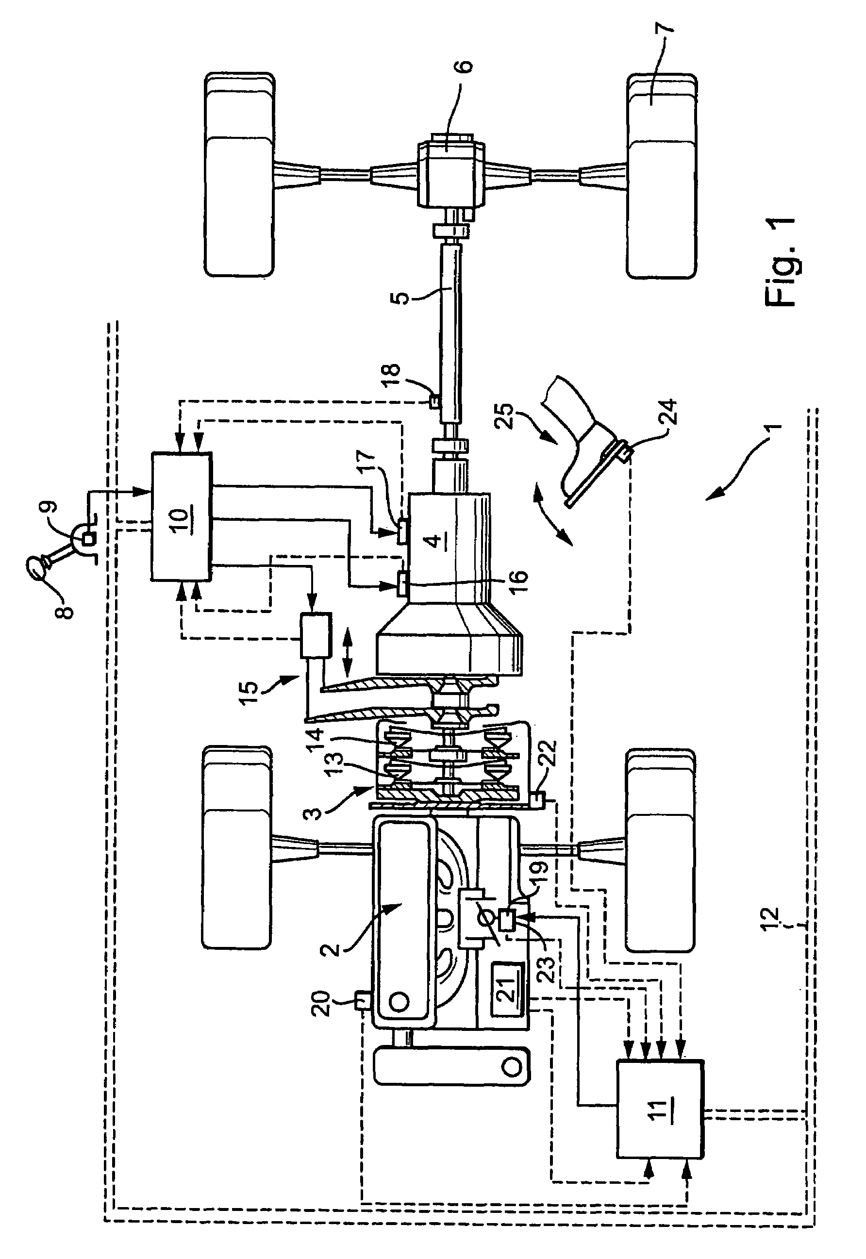
[0026]FIG. 1 schematically depicts a motor vehicle 1 having a drive train, including a driving engine 2 designed as a combustion engine, a clutch assembly 3, and a transmission 4. Wheels 7 of vehicle 1 are driven via a drive shaft 5 and a differential gear 6. It may, of course, correspondingly concern a vehicle having one or more different driven axles.

[0027]A gear-ratio selector 8, such as selector lever having sensor 9, and a control device 10, 11 are illustrated in a block diagram. Control device 10, 11 may be designed as a unit or in structurally and / or functionally separate sections. If control device 10, 11 is designed in structurally and / or functionally separate sections, these may be interconnected, for example, via a CAN-bus 12 or another electrical connection for exchanging data. Control device 10, 11 controls, for example, the automated actuation of transmission 4 and / or clutches 13, 14 belonging to clutch assembly 3, or engine 2, for example the engine torque, the gear r...


PUM


Abstract

A drive train having a clutch assembly for transmitting torque between an engine and a transmission. The clutch assembly is selectable for transmitting torque between the engine and the transmission and includes at least one friction clutch, the clutch assembly being supported on the transmission housing so that the clutch assembly is radially fixed and displaceable in an axially limited manner.

Description

CROSS REFERENCE TO RELATED APPLICATIONS[0001]This application is a continuation of U.S. patent application Ser. No. 10 / 847,748, filed on May 18, 2004, now abandoned which claims priority to German Patent Application Nos. 103 22 618.4 and 10326599.6, both of which are hereby incorporated by reference herein.[0002]The present invention is directed to a drive train having a clutch assembly for transmitting torque between an engine and a transmission. The present invention is directed, in particular, to such clutch assemblies which include at least one friction clutch for connecting and disconnecting the engine and the transmission to and from one another in terms of drive operation.BACKGROUND[0003]Clutch assemblies having two friction clutches are known, for example, from the German Application DE 28 30 659 A1, hereby incorporated by reference herein. However, such clutch assemblies have a very complex and expensive design, which also necessitates a very complex actuating system. Typic...

Claims


Application Information

Patent Timeline
Patent Type & Authority Patents(United States)
IPC IPC(8): B60K17/02F16D13/58B60K23/02F16D13/46F16D21/06F16D25/12
CPCB60K23/02F16D21/06F16D2021/0684A21C11/20A21C1/065A21C1/141A21C11/10
Inventor MEINHARD, ROLFSCHNEIDER, MATTHIAS
Owner SCHAEFFLER TECH AG & CO KG
Why Eureka
Try Eureka