

Method for manufacturing a birefringent film
a manufacturing method and film technology, applied in the direction of polarizing elements, instruments, transportation and packaging, etc., can solve the problems of deterioration of film transparency, inability to achieve retardation value, and difficulty in achieving the effect of reducing the thickness of optical film, and reducing the amount of solvent remaining
- Summary
- Abstract
- Description
- Claims
- Application Information
AI Technical Summary
Benefits of technology
Problems solved by technology
Method used
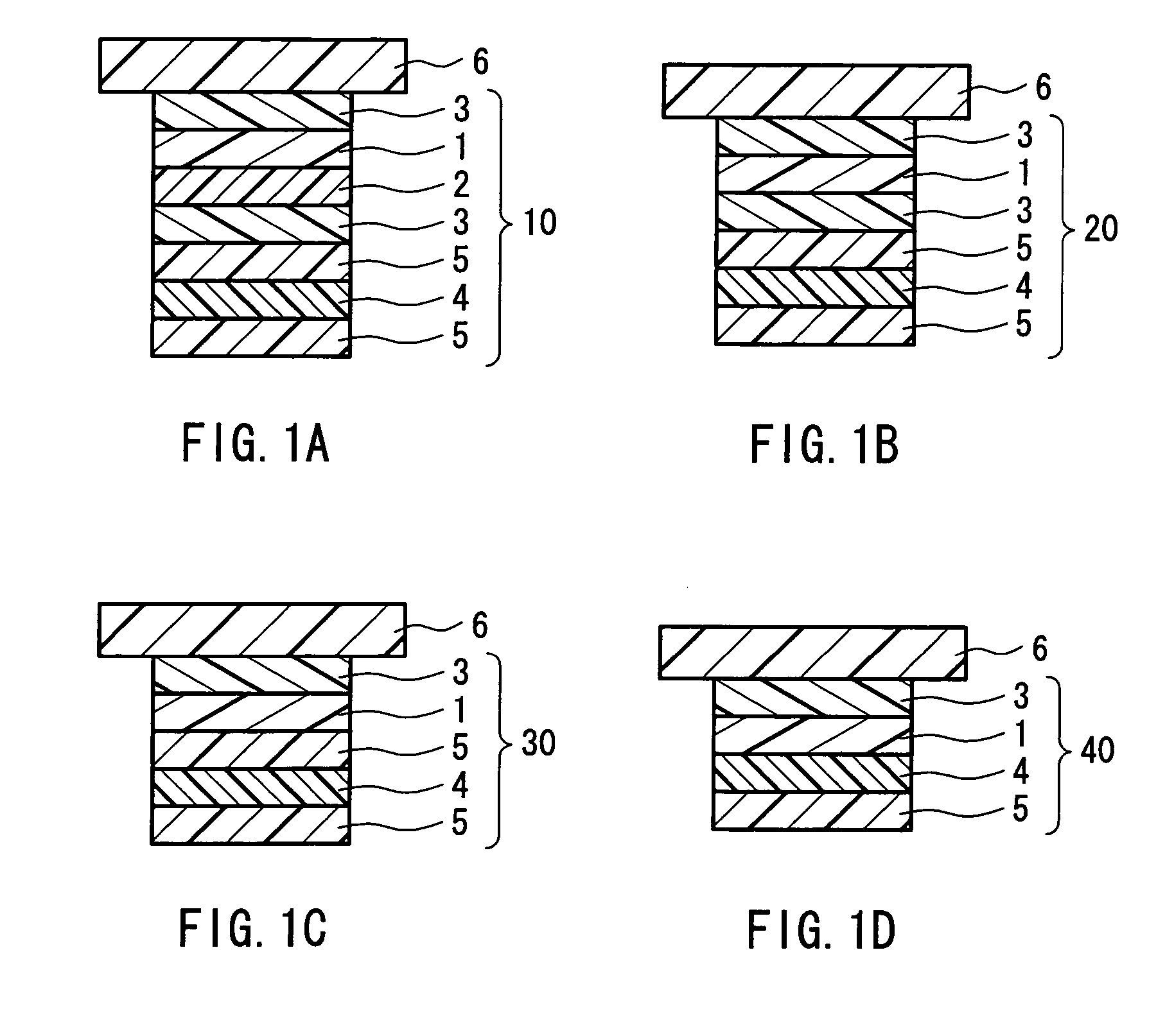
Image

Examples
example 1
Method for Measuring Optical Characteristics
[0146]Optical characteristics of each of the birefringent films obtained in Examples and Comparative examples were measured in the state where the birefringent film was laminated with a glass plate, after being transferred onto a glass plate using an acrylic adhesive so as to peel off from the base. An in-plane retardation value Δnd=(nx−ny)×d of the birefringent film and a retardation value Rth=(nx−nz)×d in a thickness direction of the film were measured at a measurement wavelength λ of 590 nm, using an automatic retardation analyzer (trade name: KOBRA-21ADH, manufactured by Oji Scientific Instruments). Optical characteristics of the glass plates measured beforehand were substantially isotropic both in its in-plane direction and its thickness direction. The amount of change in Rth, which shows thermal stability of the Rth, was obtained by measuring a difference of the retardation value in the thickness direction before and after heating th...
example 2
[0153]A polyimide solution that was the same as the polyimide solution of Example 1 was applied onto a TAC film base that was the same as the TAC film base of Example 1, and was heated at 100° C. for 30 minutes, thereafter, was dried by heat at 180° C. for 30 minutes so as to obtain a birefringent film with a negative uniaxiality. Next, this birefringent film was stretched in the same manners as Example 1, thereby obtaining, on the stretched base, a birefringent film with an optical biaxiality having a thickness of 6.0 μm. Optical characteristics of this birefringent film were: Δnd=50.9 nm; Rth=271.8 nm; and (nx−nz) / (nx−ny)=5.3. The amount of a remaining solvent was 0.73 wt %.
example 3
[0154]A polyimide solution that was the same as the polyimide solution of Example 1 was applied onto a TAC film base that was the same as the TAC film base of Example 1, and was heated at 120° C. for 30 minutes, thereafter, was dried by heat at 180° C. for 30 minutes so as to obtain a birefringent film with a negative uniaxiality. Next, this birefringent film was stretched in the same manner as Example 1, thereby obtaining, on the stretched base, a birefringent film with an optical biaxiality having a thickness of 6.0 μm. Optical characteristics of this birefringent film were: Δnd=50.1 nm; Rth=270.5 nm; and (nx−nz) / (nx−ny)=5.4. The amount of a remaining solvent was 0.69 wt %.
PUM
| Property | Measurement | Unit |
|---|---|---|
| temperature | aaaaa | aaaaa |
| temperature | aaaaa | aaaaa |
| thickness | aaaaa | aaaaa |
Abstract
Description
Claims
Application Information