Magnetoresistive effect element having hard magnetic films in non-uniform cross-sectional shape

a magnetic film, non-uniform cross-sectional technology, applied in the field of magnetic effect sensors, can solve the problems of insufficient change in magnetoresistance, difficult to form such a sv film configuration, change in magnetoresistance, etc., to achieve high ratio of change in magnetoresistance, increase the reproducible output level, and increase the film thickness

Inactive Publication Date: 2009-02-24
TDK CORPARATION
View PDF35 Cites 1 Cited by
  • Summary
  • Abstract
  • Description
  • Claims
  • Application Information

AI Technical Summary

Benefits of technology

[0013]It is an object of the present invention to provide a magnetoresistive effect sensor of the CPP-GMR type having a large film thickness, which allows a high ratio of change in magnetoresistance to increase the reproduced output level, as well as to improve linear magnetic response to a signal magnetic field.
[0015]In such a magnetoresistive effect sensor, the magnetic field generated by the hard magnetic films is less apt to leak upwardly in the stacked direction beyond the first boundary line. Since the hard magnetic films extend toward the free layer ending at the end points that are each disposed substantially on the lateral side of the free layer, the magnetic field that is generated by and flows in the hard magnetic films is applied efficiently to the free layer. Furthermore, since the hard magnetic films extend toward the spin valve film such that the cross-sectional areas of the hard magnetic films in a plane perpendicular to the layer width direction become progressively smaller toward the spin valve sensor, the hard magnetic films can be formed in a sufficient thickness in areas remote from the spin valve sensor, so that a sufficient magnetic field can be generated in those areas. In the vicinity of the spin valve sensor, the magnetic field that is generated from hard magnetic layers is concentrated on the free layer.
[0023]According to the present invention, a magnetoresistive effect sensor of a CPP-GMR type having a large film thickness can be provided which exhibits a high ratio of change in magnetoresistance to increase reproduced output level, as well as enhanced linear magnetic response to a signal magnetic field.

Problems solved by technology

As a result, the spin-dependent scattering of conductive electrons changes depending on the relative angle, causing change in magnetoresistance.
However, since the sense current flows perpendicularly to the film planes, i.e., the film boundaries, it is difficult for CPP-GMR sensors to obtain sufficient spin-dependent scattering at the film boundaries, which may lead to insufficient change in magnetoresistance.
In a CPP-GMR sensor, however, it is difficult to form such a SV film configuration as shown in FIG. 2, because the SV film needs to be formed in a rather larger thickness.
In hard magnetic films that have such a structure, the magnetic field generated by the hard magnetic films is not directed toward the free layer, but towards the upper electrode / shield layer, and fails to the apply biasing magnetic field effectively to the free layer.
This makes it difficult to increase the reproduced output level and to obtain a linear magnetic response to the signal magnetic field.
In addition, the magnetic characteristics of the upper electrode / shield layer are adversely affected.
These drawbacks cannot be resolved by the above-disclosed conventional techniques.
However, it becomes more difficult to form such a structure as the thickness of the SV film increases.
It may be effective to increase the thickness of the hard magnetic films in order to reduce the projection above the SV film, which, however, tends to apply an excessive biasing magnetic field, resulting in a reduction in the reproduced output level.
Disposing hard magnetic films only around a free layer, as disclosed in Document 3, may result in an insufficient biasing magnetic field due to the insufficient thickness.

Method used


Image

  • Magnetoresistive effect element having hard magnetic films in non-uniform cross-sectional shape
  • Magnetoresistive effect element having hard magnetic films in non-uniform cross-sectional shape
  • Magnetoresistive effect element having hard magnetic films in non-uniform cross-sectional shape

Examples


Embodiment Construction

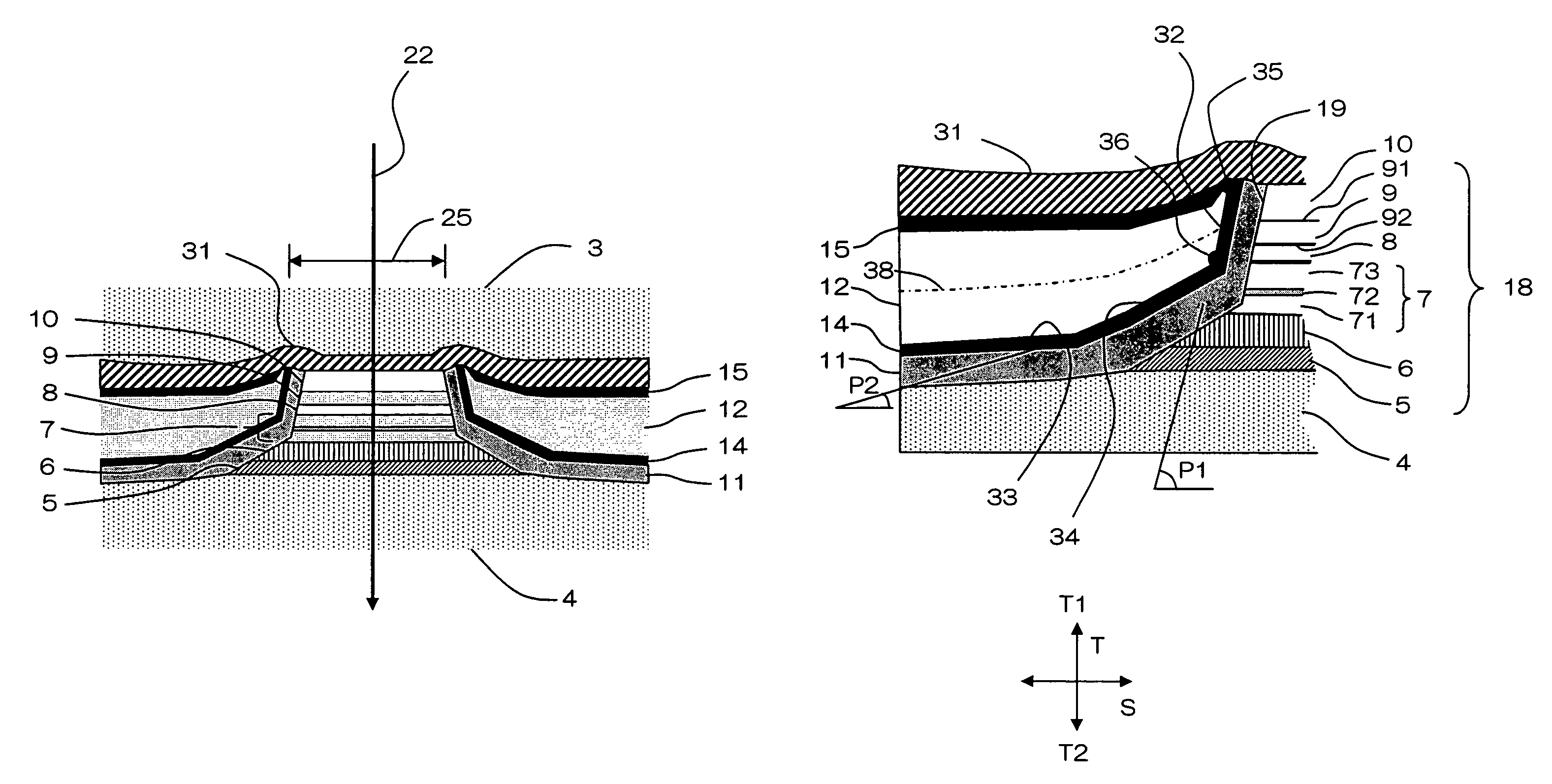
[0035]A magnetoresistive effect sensor, hereinafter referred to as CPP sensor 2, according to the present invention will be described with reference to the drawings.

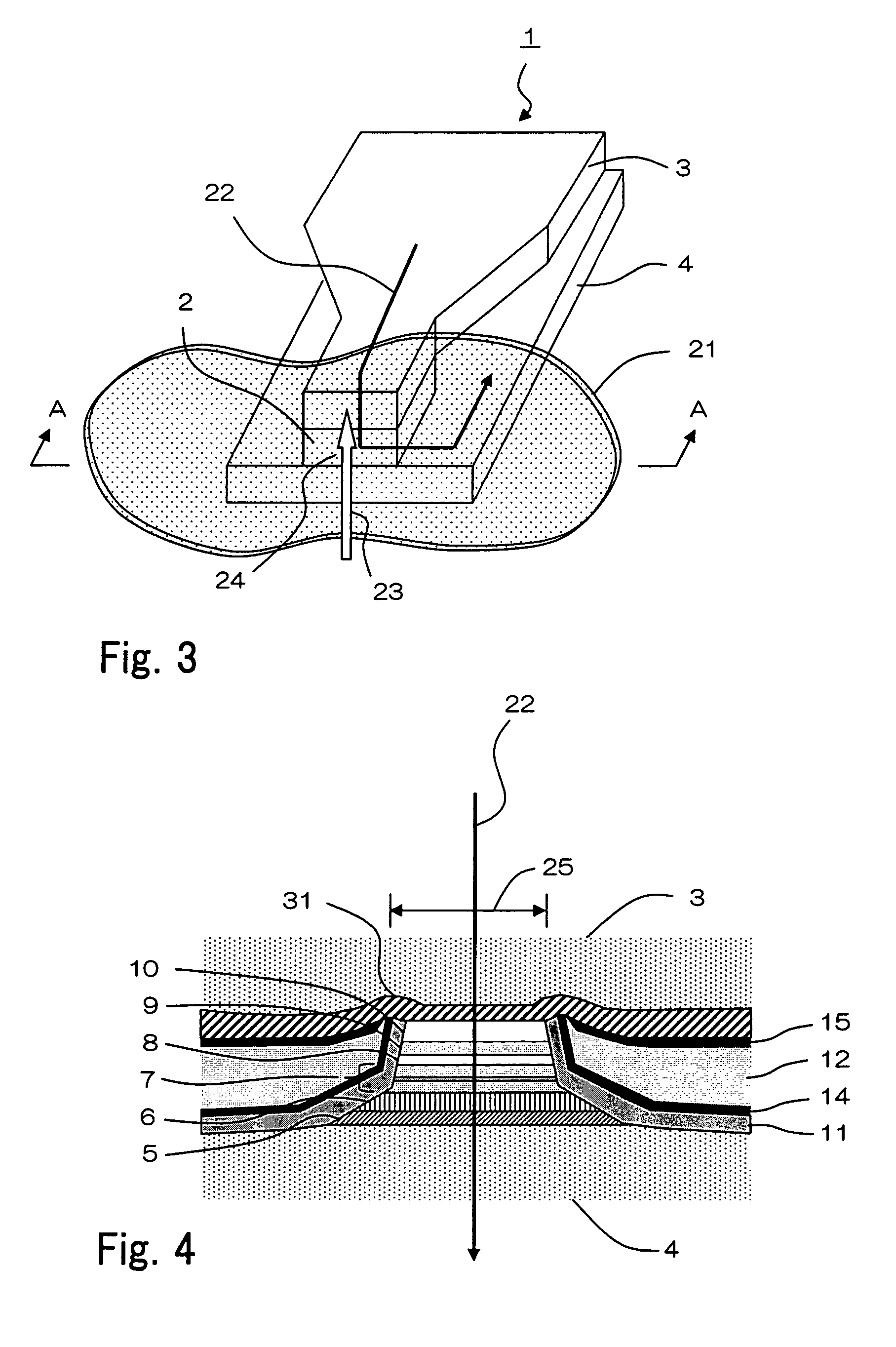
[0036]FIG. 3 shows thin-film magnetic head 1 incorporating a magnetoresistive effect sensor according to the present invention in a perspective view. Thin-film magnetic head 1 may be a read-only head or an MR / inductive composite head which has a read head portion and a write head portion. CPP sensor 2 is sandwiched between upper electrode / shield layer 3 and lower electrode / shield layer 4, with an end portion facing recording medium 21. The end portion of CPP sensor 2 defines a part of air bearing surface 24. As indicated by the solid arrow in FIG. 3, sense current 22 flows from upper electrode / shield layer 3 through CPP sensor 2 to lower electrode / shield layer 4 under a voltage applied between upper electrode / shield layer 3 and lower electrode / shield layer 4. The signal magnetic field of recording medium 21 in a region o...


PUM

PropertyMeasurementUnit
thicknessaaaaaaaaaa
widthaaaaaaaaaa
thicknessaaaaaaaaaa

Abstract

A magnetoresistive effect sensor includes a pinned layer, a nonmagnetic spacer layer, and a free layer having a total thickness of at least 10 nm. The sensor has insulating films disposed on both side surfaces of the spin valve film. The sensor has hard magnetic films disposed on the insulating films for applying a biasing magnetic field to the free layer. Each hard magnetic film extends toward the free layer in a vicinity of the spin valve film, such that as each hard magnetic film extends toward the spin valve film, a cross-sectional area thereof in a plane perpendicular to the layer width direction becomes progressively smaller. Each hard magnetic film has, in a plane parallel to the air bearing surface, a first boundary line which at least partially faces the free layer and substantially defines an end point of the hard magnetic film in the layer width direction.

Description

BACKGROUND OF THE INVENTION[0001]1. Field of the Invention[0002]The present invention relates to a magnetoresistive effect sensor, a thin-film magnetic head, a head gimbal assembly, and a hard disk device, and more particularly to a magnetoresistive effect sensor for use in a thin-film magnetic head of a magnetic recording device such as a hard disk device etc.[0003]2. Description of the Related Art[0004]Magnetic heads employing a GMR (Giant Magneto-Resistive) sensor as a reproducing sensor have been widely used in high-density magnetic recording applications. In particular, a GMR sensor which employs a spin valve film (hereinafter referred to as an SV film) exhibits a high ratio of resistance change to sense current that flows through the GMR sensor in order to read information recorded in a recording medium. It is therefore possible for a GMR sensor to provide a magnetic head of higher sensitivity. An SV film is a stacked layer structure comprising a ferromagnetic layer having a f...

Claims


Application Information

Patent Timeline
Patent Type & Authority Patents(United States)
IPC IPC(8): G11B5/39G01R33/02
CPCB82Y10/00B82Y25/00G01R33/093G11B5/3932G11B5/398H01L43/08G11B2005/3996H10N50/10
Inventor MIYAUCHI, DAISUKESATO, KAZUKIKANAYA, TAKAYASU
Owner TDK CORPARATION
Why Eureka
Try Eureka