PWM cycloconverter

a cycloconverter and cycloconverter technology, applied in the field of cycloconverters, can solve the problems of large variation in condenser voltage and limited correction quantity, and achieve the effects of improving the control performance of a cycloconverter, reducing the number of corrections, and improving the input current waveform

Inactive Publication Date: 2009-02-24
YASKAWA DENKI KK
View PDF24 Cites 2 Cited by
  • Summary
  • Abstract
  • Description
  • Claims
  • Application Information

AI Technical Summary

Benefits of technology

[0011]Applying the invention allows improvement of an input current waveform and regeneration of energy of a snubber into a power source in a PWM cycloconverter to be easily performed.
[0012]On the basis of the principle of a PWM cycloconverter, an input current waveform can be originally controlled. An input unit, however, is directly connected to an output unit by means of a bi-directional semiconductor switch, so that output current should be simultaneously controlled. This causes a limitation in input current controlling performance. The invention relates to an assistant device for improving the controlling performance of a PWM cycloconverter. In accordance with the invention, a typical and small-sized PWM converter is applied for the purpose of easily achieving input current control.

Problems solved by technology

Accordingly, applying electric current more than the quantity equal to correction of a resonance component adversely causes large variation in condenser voltage, and therefore, quantity of correction is limited.

Method used


Image

  • PWM cycloconverter
  • PWM cycloconverter
  • PWM cycloconverter

Examples


embodiments

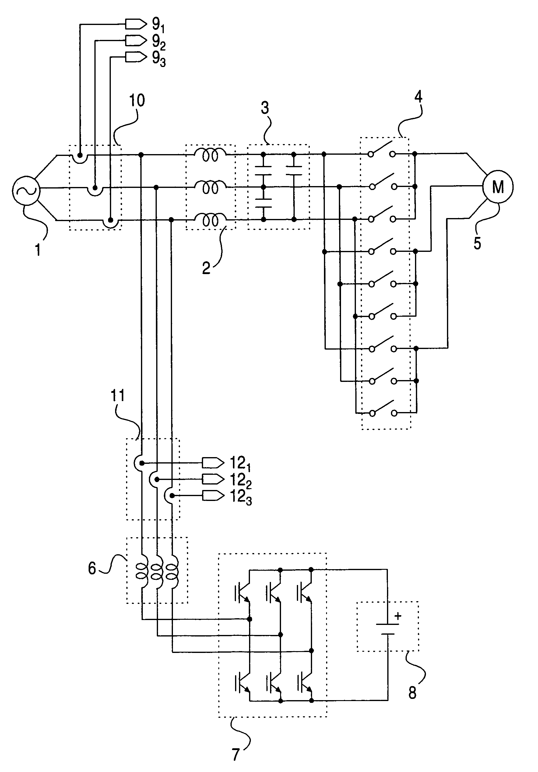
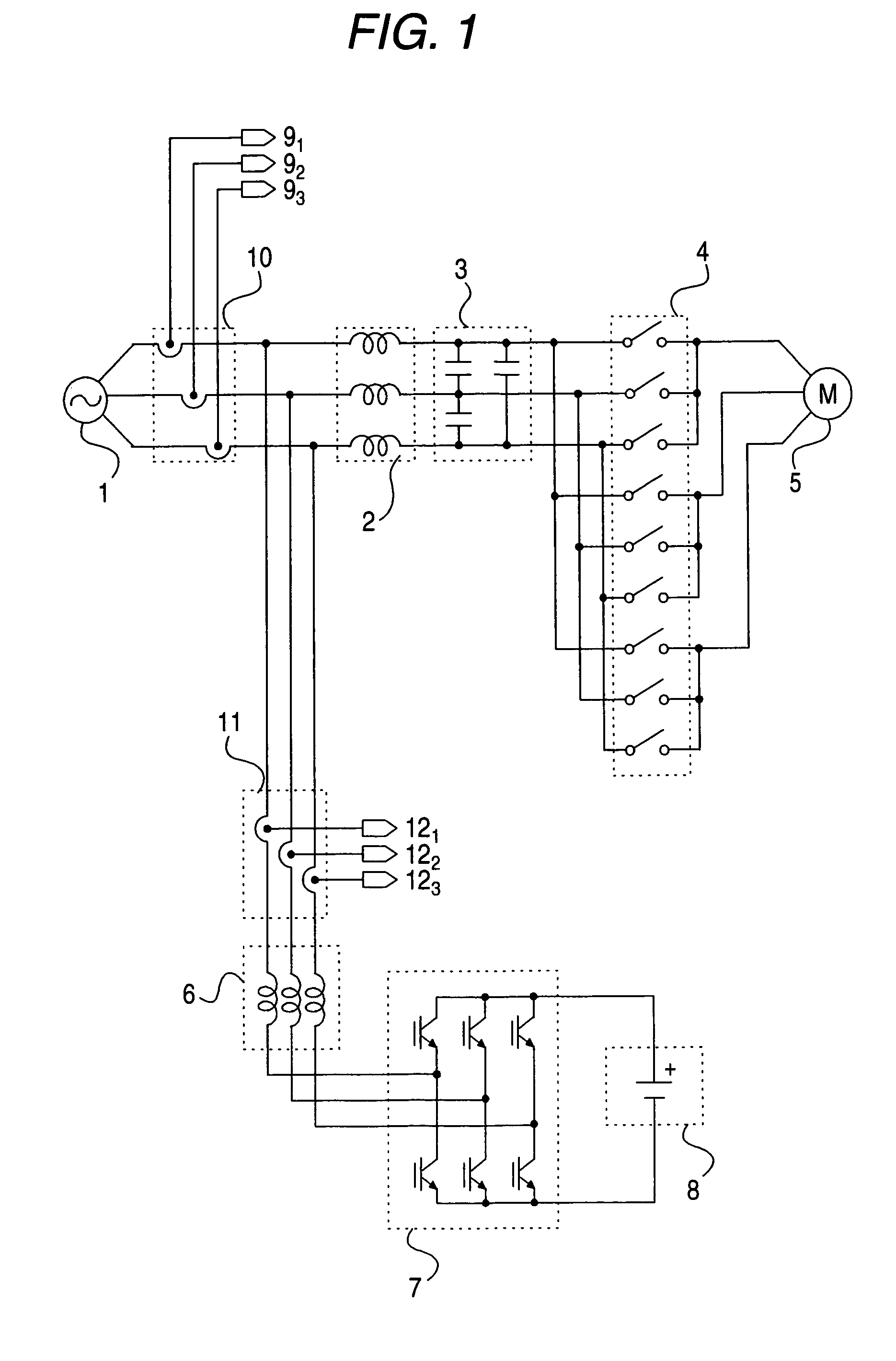
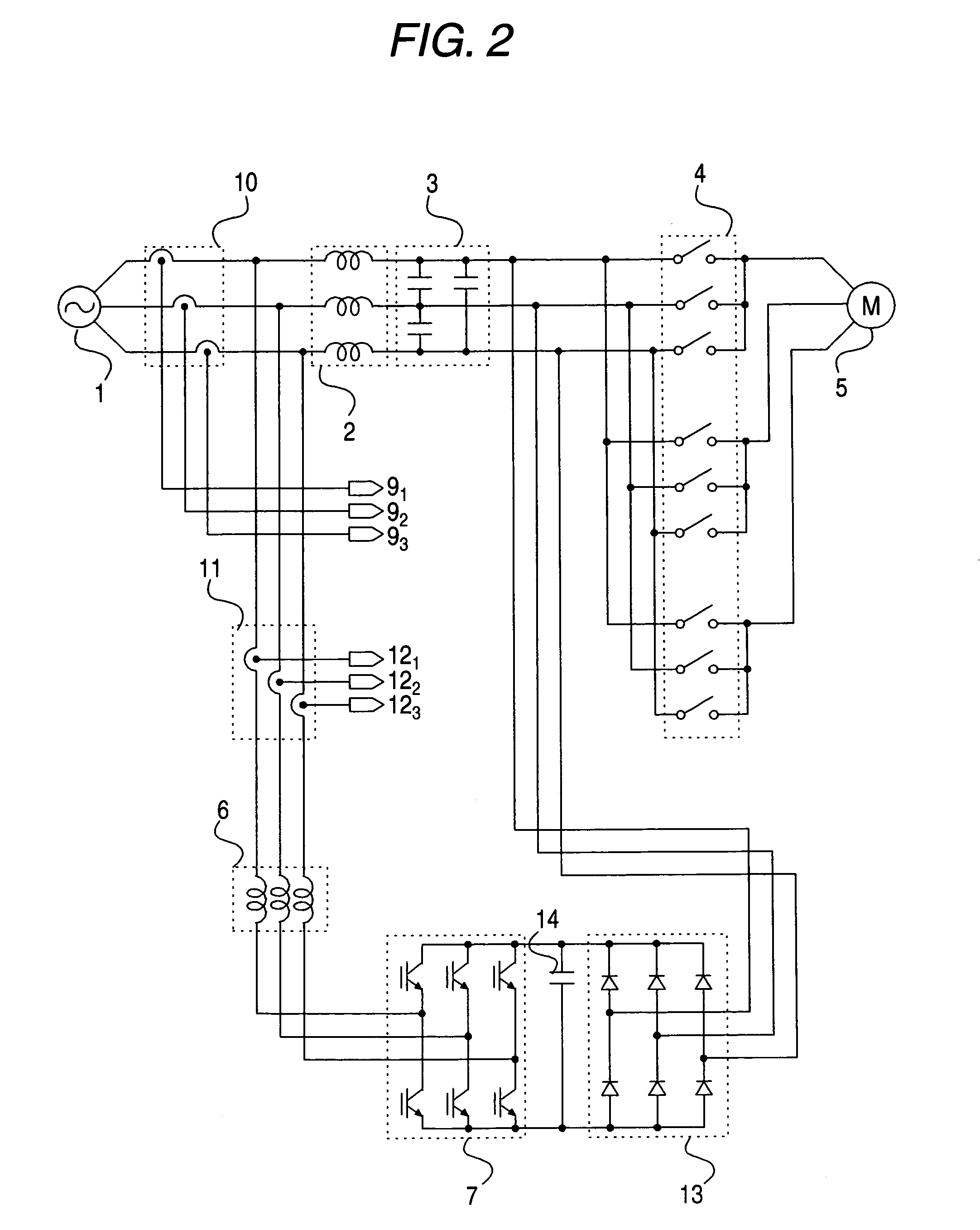
[0037]FIG. 1 shows a PWM cycloconverter and a system structure including a PWM converter using a DC voltage source in a mode for carrying out the invention. FIG. 2 shows a PWM cycloconverter and a system structure including a PWM converter using a diode rectifying circuit in a mode for carrying out the invention. FIG. 3 shows a PWM cycloconverter and a system structure including a PWM converter using a DC voltage source formed from a snubber circuit in a mode for carrying out the invention. FIG. 4 shows an example of a structure of a snubber circuit in a mode for carrying out the invention. FIG. 5 shows an example of a structure of a snubber circuit in a mode for carrying out the invention. FIG. 6 shows an example of a conventional system structure of a PWM cycloconverter and a conventional method of keeping down filter resonance.

[0038]In a system structure using a PWM converter in FIG. 1, elements under the same names as those in FIG. 6 showing a conventional embodiment are marked ...


PUM


Abstract

A PWM cycloconverter easily capable of improving an input current waveform and regenerating energy of a snubber into a power source is provided.A PWM cycloconverter includes a PWM converter connected to a DC voltage system. An output unit of the PWM converter is connected to a place before an input filter of the PWM cycloconverter to keep down resonance of the input filter.

Description

TECHNICAL FIELD[0001]The invention relates to a PWM cycloconverter in which using a PWM converter connected to an input unit of the PWM cycloconverter allows an arbitrary electric current waveform to be achieved so that input current distortion can be kept down.BACKGROUND ART[0002]FIG. 6 shows a system of a conventional PWM cycloconverter. In FIG. 6, 1 denotes a three-phase AC power source, 2 denotes a three-phase AC reactor, 3 denotes a three-phase AC capacitor, 4 denotes a bi-directional switch group, 5 denotes a motor functioning as a load, 6 denotes a three-phase AC reactor, 7 denotes a PWM converter for converting AC into DC, 14 denotes a smoothing capacitor, which is a DC voltage means, 91-3 denote a detection current signal of the three-phase AC power source, 10 denotes a CT for detecting electric current, which is a current detection means for detecting electric current of the three-phase AC power source, 11 is a CT for detecting electric current, which is a current detectio...

Claims


Application Information

Patent Timeline
Patent Type & Authority Patents(United States)
IPC IPC(8): H02M5/45H02M5/27H02J3/01H02M1/34
CPCH02J3/01H02M1/34H02M5/271H02M2001/342Y02B70/1491Y02E40/40H02M1/342Y02B70/10
Inventor HARA, HIDENORIKANG, JUNKOOYAMAMOTO, EIJIYAMADA, KENJI
Owner YASKAWA DENKI KK
Why Eureka
Try Eureka