
System for measurement of projected turbulence downwind of an aircraft

a technology for aircraft and turbulence, applied in the direction of instruments, ict adaptation, reradiation, etc., can solve the problems of not being able to obtain a total deflection of the surface, the distance between the nose and the wings cannot allow a phase advance of more than 100 ms, etc., to reduce the mass of the aircraft structure, reduce the fatigue load, and reduce the sizing charge

Inactive Publication Date: 2009-03-03
AIRBUS OPERATIONS (SAS)
View PDF12 Cites 14 Cited by
  • Summary
  • Abstract
  • Description
  • Claims
  • Application Information

AI Technical Summary

Benefits of technology

The invention is a system that uses a lidar to measure wind speed in front of an aircraft to improve its control and comfort. The system aims to overcome the limitations of conventional systems by measuring wind speed in a more accurate way. The lidar transmits an optical beam and receives a backscattered optical beam to detect variations in wind speed. The system uses a direct detection system and a single laser to obtain better performance. The wind speed data is used to determine the orders to be applied to the aircraft's control surfaces, reducing sizing charges, fatigue load, and passenger discomfort. The system can be used in open-loop or closed-loop control.

Problems solved by technology

However, even on the largest airplanes the distance between its nose and its wings does not allow for a phase advance of more than 100 ms.
With the output speed cf current actuators, it is not possible to obtain a total deflection of the surfaces, and consequently optimal efficacy in particular of the laws that reduce the loads or increase passenger comfort.

Method used


Image

  • System for measurement of projected turbulence downwind of an aircraft
  • System for measurement of projected turbulence downwind of an aircraft
  • System for measurement of projected turbulence downwind of an aircraft

Examples


Embodiment Construction

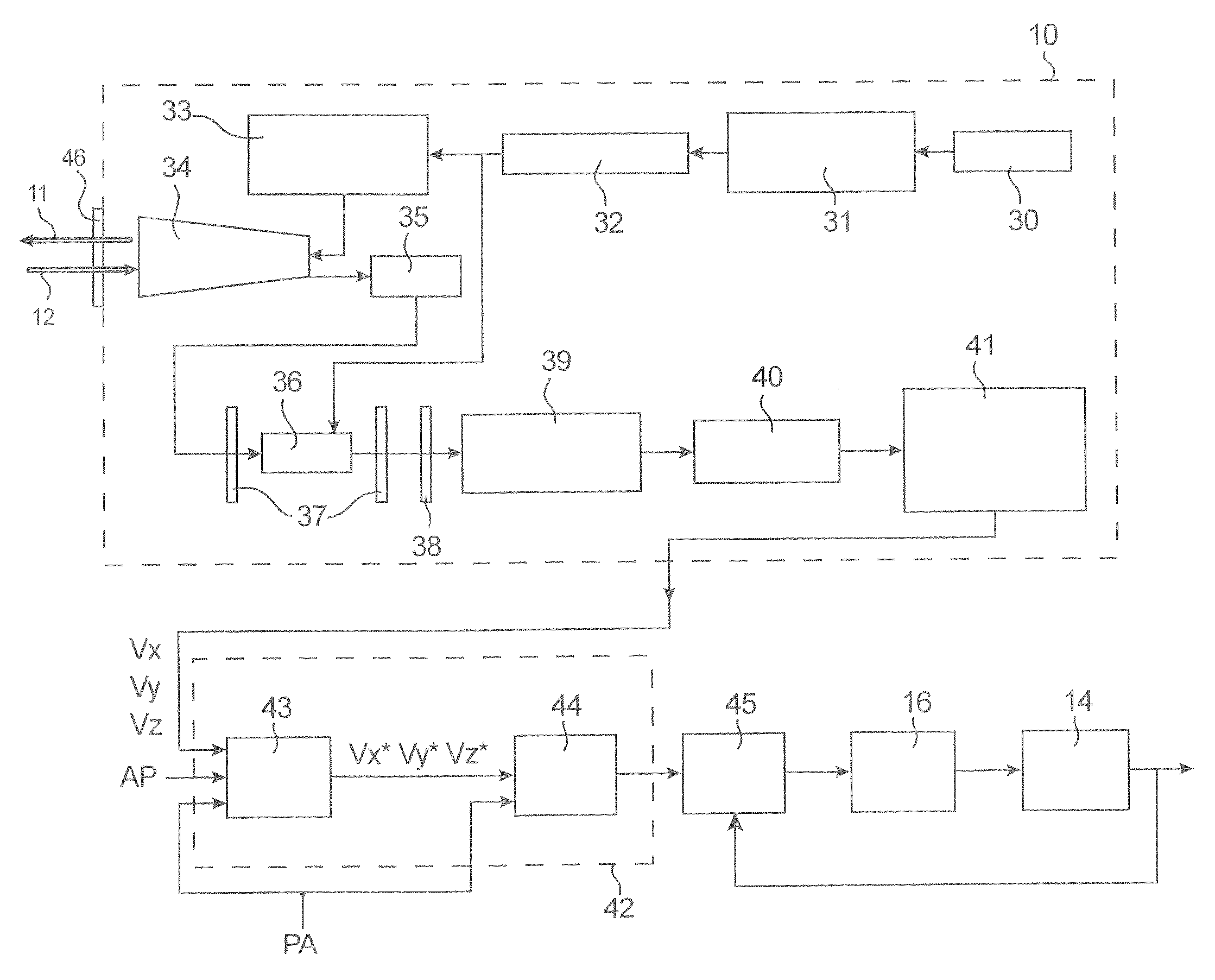
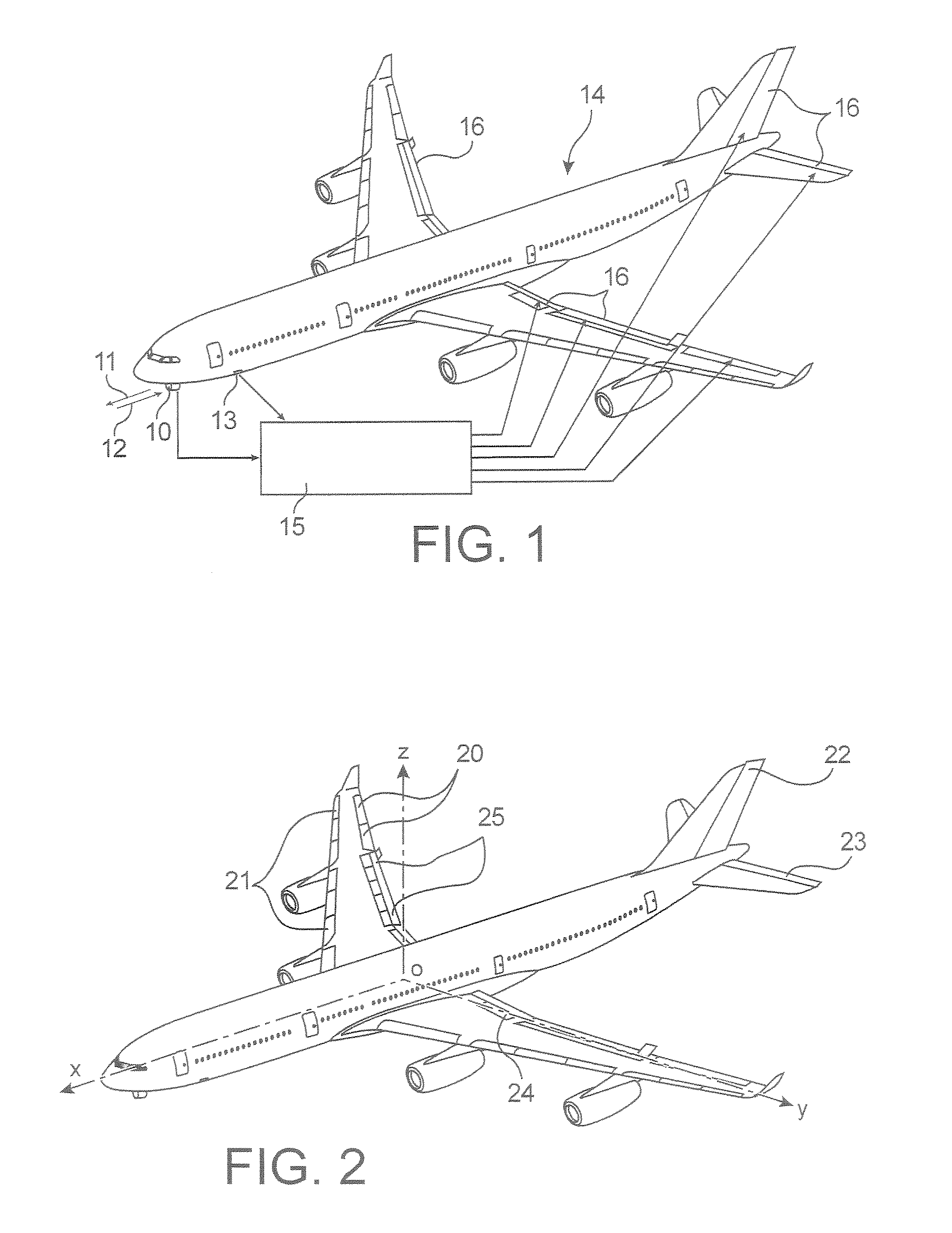
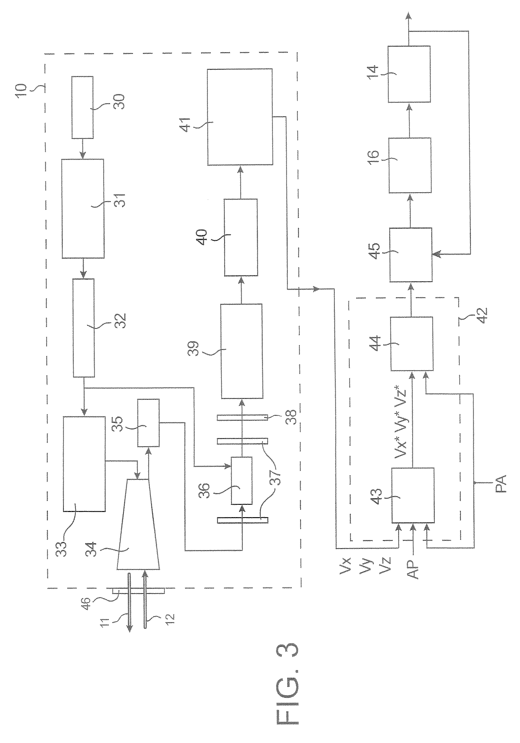
[0028]As shown in FIG. 1, in the system of the invention, the signals issued by a lidar 10, which transmits a laser beam 11 forward and receives the backscattered beam 12, as well as signals issued by sensors 13 of the airplane 14, are entered into the flight control computers 15, which give the orders to the flight control surfaces 16.

[0029]As shown in FIG. 2, these flight control surfaces 14 can thus be:

[0030]the wings 20, which are control surfaces for roll or lateral control, which give a moment with respect to the axis Ox (airplane axis),

[0031]the leading edge flaps 21, which are used at take-off and approach to back up the stall position of the wings,

[0032]the rudder 22, which is a yaw control surface or a rudder, which gives a moment with respect to the axis Oz,

[0033]the elevators 23, which are pitch control surfaces or elevators, which give a moment with respect to the axis Oy,

[0034]the “spoilers”24, which are used primarily at larding to keep the airplane on the ground and ...


PUM


Abstract

A system for anticipated measurement of turbulence upstream of an aircraft, placed on-board the aircraft, includes a lidar, an image detector, a first processing component, and a second processing component. The lidar transmits an optical beam toward a front of the aircraft and receives a backscattered optical beam. The image detector detects variations in wind speed based on the backscattered optical beam. The first processing component uses a first internal correction algorithm to calculate values of components of the wind speed. The second processing component uses a second external correction algorithm to deliver possible command signals to actuators of at least one aircraft control surface based on the calculated values of the components of the wind speed from the first internal correction algorithm.

Description

Names of Parties to a Joint Research Agreement[0001]The subject matter of the claimed invention was developed under a joint research agreement named AWIATOR. The parties to this joint research agreement include Airbus France and EADS Deutschland GmbH. Additionally parties include Alenia, CERFACS, CNRS, DLR, TU Munchen, GKN Aerospace Services Ltd., Inasco (Integrated Aerospace & Sciences Corporation O.E.), Instituto Superior Technico, Israel Aircraft Industries, NLR, Nationa Technical University of Athens, ONERA, Sonaca SA, SPASA, Sener, and Universite Catholique de Louvain. The joint research agreement began on July 1, 2002. The claimed invention is directed to a system for anticipated measurement of turbulence upstream of an aircraft including a lidar.TECHNICAL FIELD[0002]This invention relates to a system for anticipated measurement of turbulence upstream of an aircraft.[0003]Throughout the remainder of the description the aircraft will, by way of example, be considered to be an a...

Claims


Application Information

Patent Timeline
Patent Type & Authority Patents(United States)
IPC IPC(8): G01B9/02G01S17/95G05D1/06
CPCG01S17/95Y02A90/10
Inventor MIRAND, PIERRELACABANNE, MICHELAVERSA, NICKY
Owner AIRBUS OPERATIONS (SAS)
Learn More