Method for multiple antenna transmission

a transmission method and antenna technology, applied in diversity/multi-antenna systems, electromagnetic wave modulation, modulation, etc., can solve the problems of difficult to obtain similar improvements on the downlink, difficulty in using multiple antennas at the mobile handset, and large need to provide increased data rates to a large number of users

Active Publication Date: 2009-03-03
WSOU INVESTMENTS LLC +1
View PDF12 Cites 6 Cited by
  • Summary
  • Abstract
  • Description
  • Claims
  • Application Information

AI Technical Summary

Problems solved by technology

The need to provide increased data rates to a large number of users is an especially urgent problem in both the downlink (base-to-mobile) and the uplink (mobile-to-base) in third generation (3G) wideband CDMA systems.
However, similar improvements on the downlink seem to be harder to obtain.
The physical demands of antenna-array processing units make the use of multiple antennas at the mobile handset problematic.
The small size of handheld units limits both the spatial resolution of the array (because of the small number of elements), as well as the diversity gain (because the elements are close to one another).
Closed-loop techniques typically suffer from reduced reverse link capacity because of the extra channel information that is transmitted.
Moreover, open-loop techniques do not penalize the reverse link capacity as closed-loop techniques do.
In Rohani et al, the spatial diversity inherent in the channel is not fully exploited.
However, when the mobile is stuck in a deep fade on a slow-fading channel, any temporal diversity advantage is lost.
These extra resources limit the overall efficiency of the system.
A disadvantage of this method is the need for constant measurement and feedback of the channel characteristics and the subsequent recalculation of the adaptive array weights used to modify signals for each antenna element.
Thus, the feedback loop in the adaptive array or beamforming technique cannot keep up with a quickly changing channel between the base station and a high-speed mobile station.

Method used


Image

  • Method for multiple antenna transmission
  • Method for multiple antenna transmission
  • Method for multiple antenna transmission

Examples


Embodiment Construction

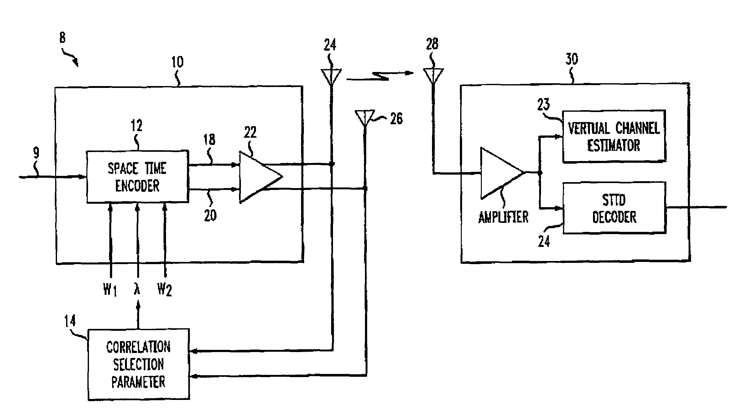
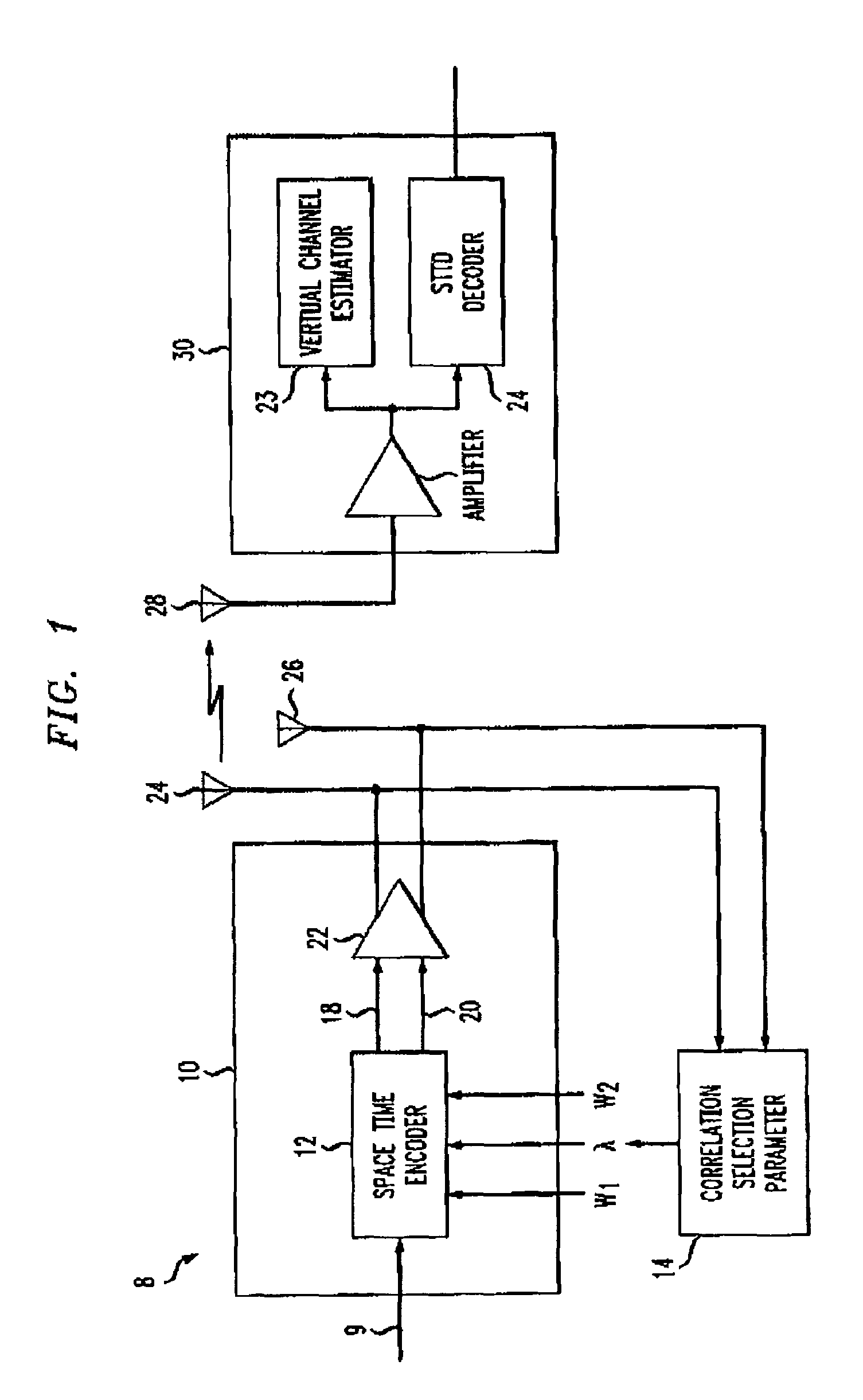
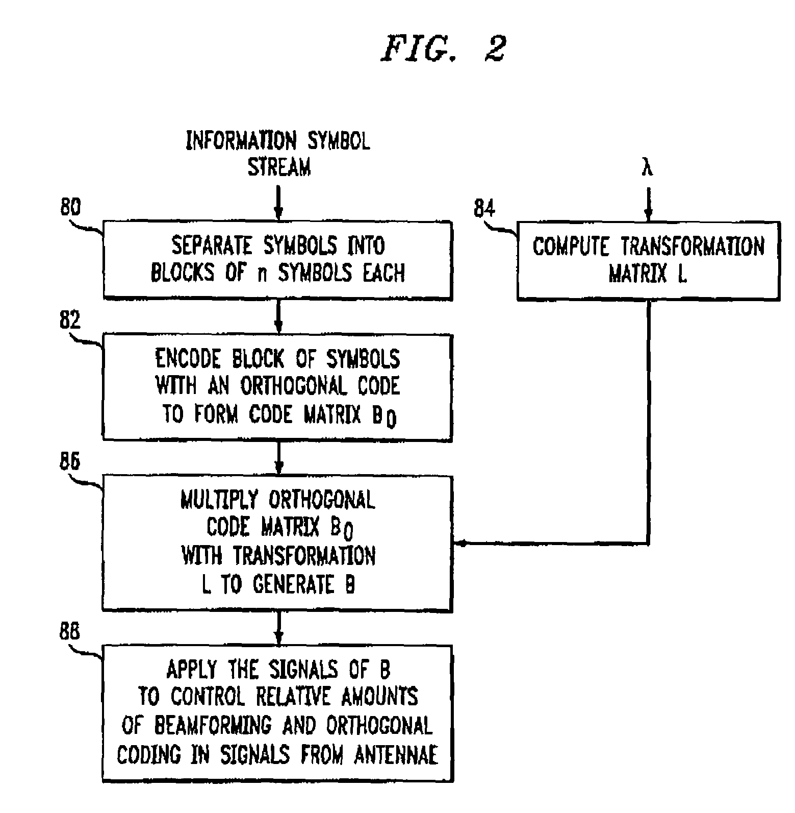
[0017]Beamforming and orthogonal space-time coding (such as space time transmit diversity (STTD) or a variant of STTD) are two methods being studied for transmission using multiple antennas due to the potentially significant diversity and / or array gains that can be obtained. With beamforming, the signals transmitted by the different antennae differ only by a complex scaling factor, designed such that the signals add constructively at the intended receiver. With orthogonal space-time coding, the signals transmitted by the different antennae are orthogonal, in order to allow their independent demodulation.

[0018]Beamforming and orthogonal coding are representative of two very different methods used for multiple antenna transmission. Beamforming relies completely on correct channel knowledge at the transmitter whereas orthogonal coding ignores any channel information the transmitter may have. In practice, the transmitter often has some instantaneous or average knowledge of the channel, ...


PUM


Abstract

There is disclosed a duplex communication system having multiple antennae at the forward link transmitter. One method of transmitting a stream of information symbols from the antennae is by beamforming. With beamforming the transmitter typically operates in closed loop and uses channel information from the receiver to change beams in the forward link. Another approach employs orthogonal coding. Orthogonal coding can be simpler to implement because it can operate in an open loop system that is without channel knowledge at the transmitter. Each has its advantages and disadvantages. What is here disclosed is a method which is an alternative to using only beamforming or orthogonal coding. The signals transmitted from at least two antennae are by beamforming or orthogonal coding; or by beamforming in combination with orthogonal coding in a proportion that is determined by a reference value which is related to the differences between the signals from the antennae. The reference value can be related to the amplitude or phase of the signals and it can be either measured or estimated.

Description

CROSS REFERENCE TO RELATED APPLICATION[0001]Related subject matter is disclosed in the following application assigned to the same assignee hereof: U.S. patent application entitled “Method For Multiple Antenna Transmission Using Partial Channel Knowledge,” Ser. No. 09 / 851,858, filed on May 9, 2001.BACKGROUND OF THE INVENTION[0002]1. Field of the Invention[0003]This invention relates to wireless communication systems and more particularly to a method for effective wireless communication in the presence of fading and / or other degradations.[0004]2. Description of the Related Art[0005]The capacity and data rate of existing code division multiple access (CDMA) systems can be increased by using multiple antennas at the transmitter. The need to provide increased data rates to a large number of users is an especially urgent problem in both the downlink (base-to-mobile) and the uplink (mobile-to-base) in third generation (3G) wideband CDMA systems. Antenna arrays have been often proposed as a...

Claims


Application Information

Patent Timeline
Patent Type & Authority Patents(United States)
IPC IPC(8): H04L27/00H04K1/02H04B7/06H04B7/26H04L1/00H04L1/06
CPCH04B7/0634H04B7/0656H04L1/0001H04L1/0618H04B7/0617H04B7/0689
Inventor GOLLAMUDI, SRIDHAR
Owner WSOU INVESTMENTS LLC
Why Eureka
Try Eureka