Speed nut and drive gear assembly

a technology of gear assembly and speed nut, which is applied in the direction of gearing, hoisting equipment, manufacturing tools, etc., can solve the problems of slow and tedious operation

Inactive Publication Date: 2009-03-10
THE UNITED STATES OF AMERICA AS REPRESENTED BY THE SECRETARY OF THE NAVY
View PDF23 Cites 22 Cited by
  • Summary
  • Abstract
  • Description
  • Claims
  • Application Information

AI Technical Summary

Benefits of technology

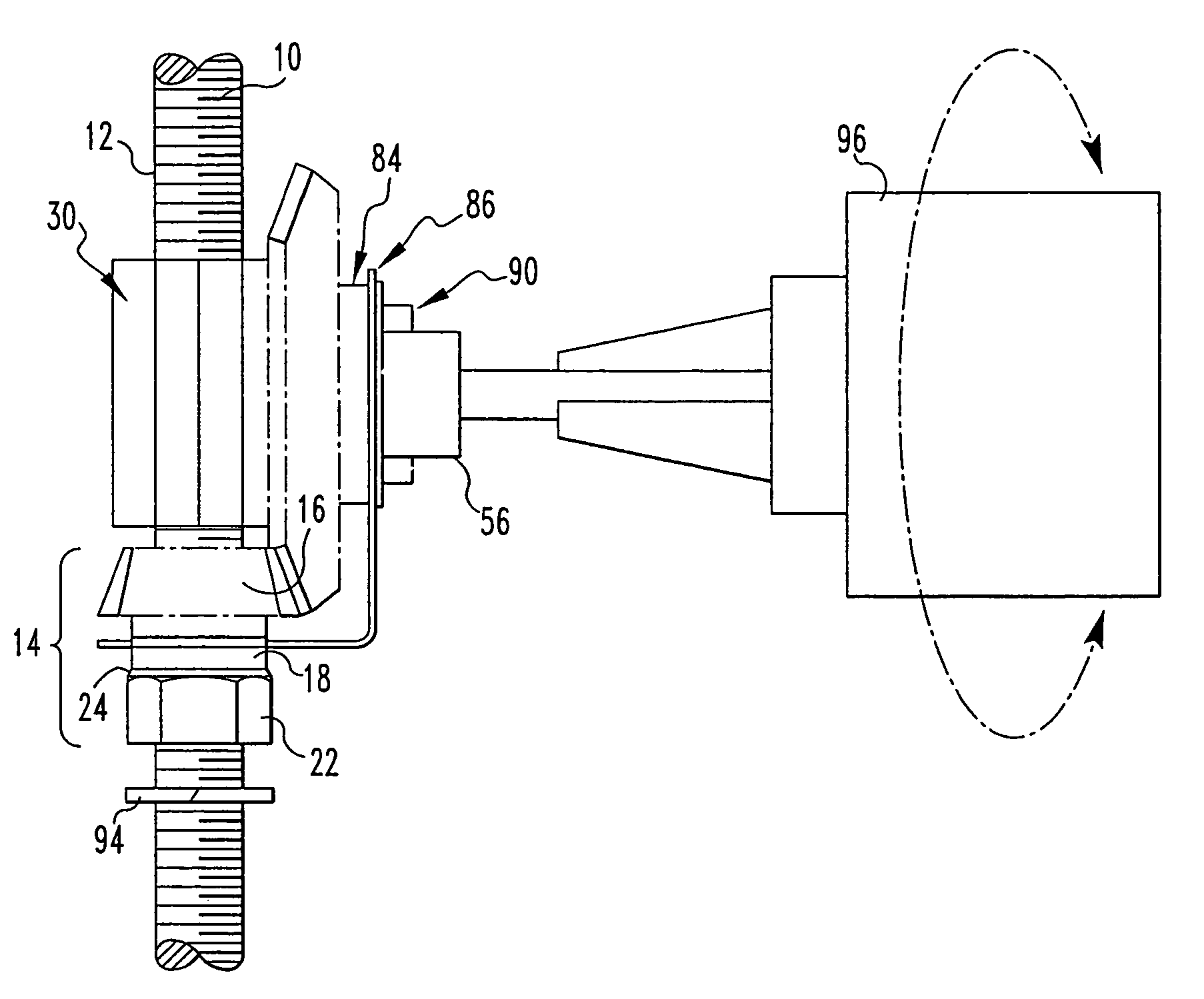
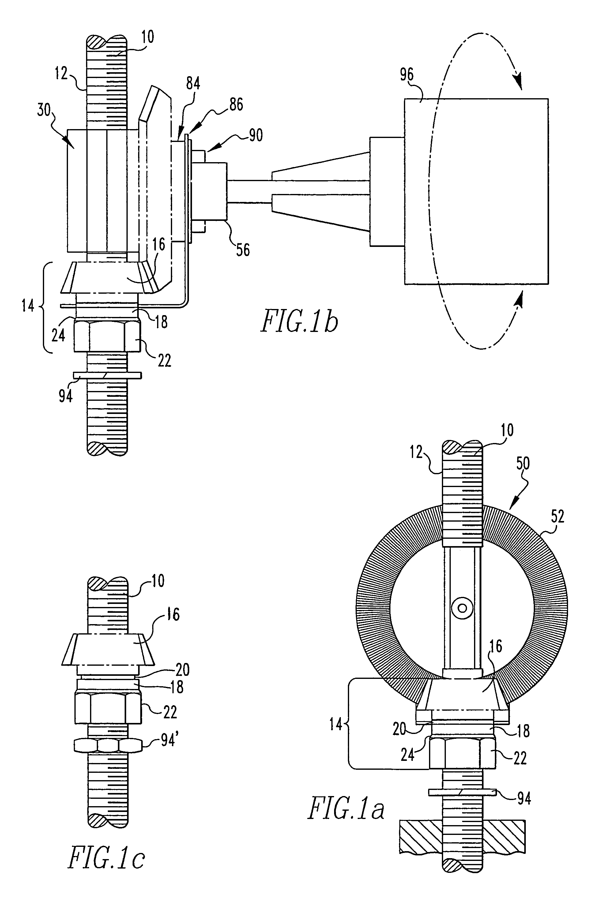
[0016]For the speed nut, the pinion is selected such that it can be rigidly attached to one side of the hex nut. The gear teeth must freely extend beyond the diameter of the nut. It is desired to select or machine the hub of the gear such that they could be welded together. A circular groove is machined in the hub of the gear to accept the fingers of 2 guides. The hole in the gear can be machined in one of two manners. It could be left as a clearance hole for the particular thread or it could be threaded to increase the contact area of the locknut. The idea of rigidly connecting the components is so that when one moves, the other follows with no time lag; and the two components have become one part.
[0017]The second component of this invention is the driver subassembly. This subassembly is the tool that is attached to the speed nut to make the adjustments. It provides a means of holding the drive gear in mesh with the pinion during operation. This driver assembly is made of the matching bevel drive gear from a gear set that had the pinion as described previously. The drive gear is modified by a threaded hole with a shoulder through the center hole, which provides a positive stop for 2 button head screws and prevent the base of the head of the screw from bottoming against the face of the gear. Thus there is a clearance for 2 spring clips such that it cannot bind the spring clip, which will be free to rotate.
[0018]A shaft is mounted into the gear with a moderate press fit and locked with a cross pin. This shaft is sized such that it can be fit into an appropriate drill chuck. The apparatus also may include a spring clip, which attaches to the face of the bevel gear with a button head screw such that it is free to rotate about the screw. This spring clip will spring open to nest and hold onto the threaded rod, which keeps the drive gear in mesh with the speed nut pinion gear while also allowing the speed nut assembly to travel along the threaded rod. There is also a small clearance between the head of the screw and the spring clip such that when the screw is bottomed out and tight, the clip is free to rotate about the screw.

Problems solved by technology

In some instances when adjustments must be made quickly, depending upon the fit of the threads and the cleanliness of the components, it can be a slow and tedious operation.

Method used


Image

  • Speed nut and drive gear assembly
  • Speed nut and drive gear assembly
  • Speed nut and drive gear assembly

Examples


Embodiment Construction

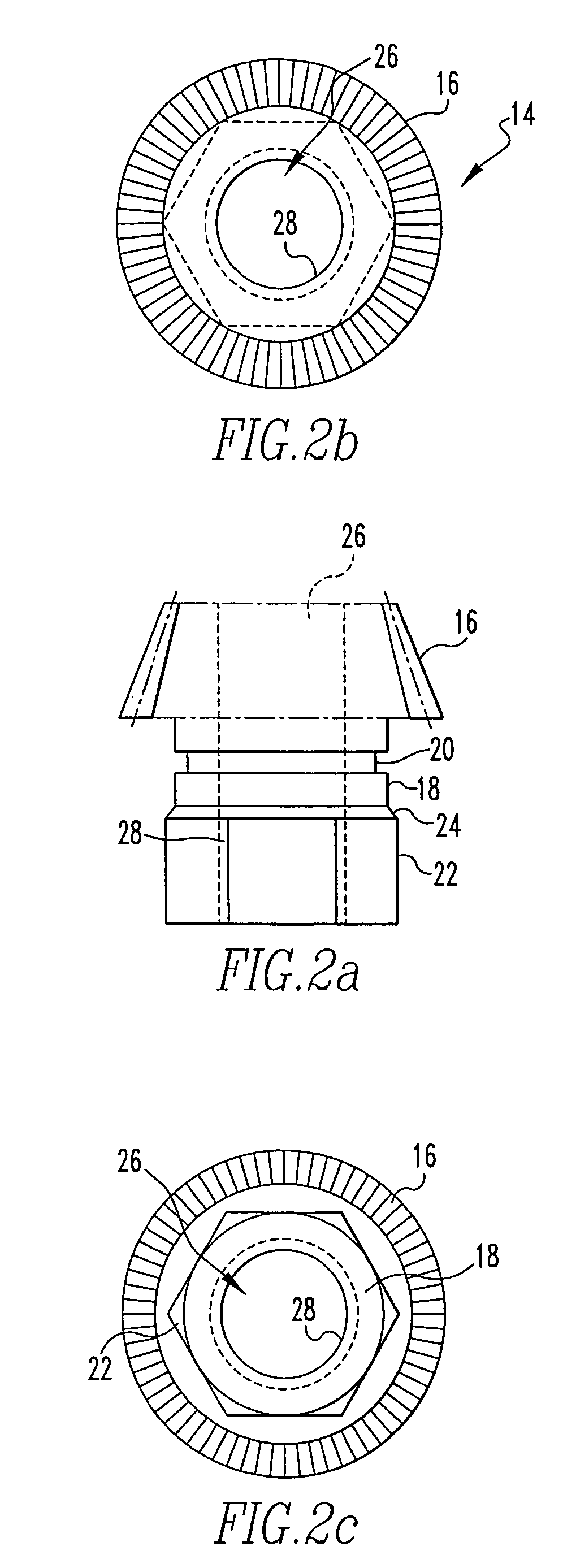
[0042]Referring to FIGS. 1a-1b and 2a-2c, the assembly of the present invention includes a cylindrical rod 10. A helical thread 12 (or any other suitable threading arrangement known to those skilled in the art) can be applied to the outer peripheral surface of the cylindrical rod 10. The assembly also includes a speed nut 14 which has a pinion bevel gear 16 superimposed on a cylindrical gear base 18. This cylindrical gear base 18 also includes a guide groove 20. The pinion bevel gear 16 and cylindrical gear base 18 are superimposed on a hex nut 22. The cylindrical gear base 18 is attached to the hex nut 22 by means of weld 24. A central axial aperture 26 extends downwardly through the pinion bevel gear 16, cylindrical gear base 18 and hex nut 22. The axial aperture 26 inside the hex nut 22 is provided with threads, or a helical groove 28.

[0043]Referring particularly to FIGS. 1a-1b and FIGS. 3a-4b, the assembly also includes a clip 30. This clip 30 includes front edges 32 and 34, tha...


PUM


Abstract

An assembly which includes a rod having an outer peripheral surface. There is also a nut having an axial aperture with an inner peripheral surface moveably engageable with the peripheral surface on the outer peripheral surface of the rod and having a peripheral gear surface. There is also a circular drive gear, which engages the peripheral gear surface of the nut. The circular drive gear is rotatable about its central axis so that the nut is moved along the outer peripheral surface of the cylindrical rod.

Description

STATEMENT OF GOVERNMENT INTEREST[0001]The invention described herein may be manufactured and used by or for the Government of the United States of America for governmental purposes without the payment of any royalties thereon or therefor.BACKGROUND OF THE INVENTION[0002](1) Field of the Invention[0003]The present invention relates to lock-threaded fasteners and more particularly to devices for moving a nut along a threaded rod.[0004](2) Brief Description of the Prior Art[0005]Current techniques used are that of hand-operated tools and motions. Frequently a wrench is used to loosen a locknut or stopnut and then the loose nut is turned by hand to some position along a threaded rod. The purpose of the locknut is to prevent movement of some mechanical device against vibration or other movement. For example, the locknut may be used for alignment or adjustment purposes, such as in varying the height of some components off a platform or base. Once the locknut has been loosened, it must be ...

Claims


Application Information

Patent Timeline
Patent Type & Authority Patents(United States)
IPC IPC(8): F16H1/24
CPCB25B13/48B25B21/002B25B17/00Y10T74/19702
Inventor MACIEJEWSKI, WENDELL C.
Owner THE UNITED STATES OF AMERICA AS REPRESENTED BY THE SECRETARY OF THE NAVY
Why Eureka
Try Eureka