Internal combustion engine

a combustion engine and internal combustion technology, applied in combustion engines, engines with oscillating pistons, positive displacement engines, etc., can solve the problems of significant mass, limited crank shaft maximum rotational speed, and two-cycle engines are must less efficient than four-cycle engines, so as to achieve constant rotational speed, high power output to weight ratio, and the effect of rotating faster

Inactive Publication Date: 2009-03-10
KARNES DYNO REV ENGINE
View PDF20 Cites 10 Cited by
  • Summary
  • Abstract
  • Description
  • Claims
  • Application Information

AI Technical Summary

Benefits of technology

[0019]The internal combustion engine operates on a four-stroke cycle. First, as an electronic starter turns the crankshaft and wheel, the elliptical cam-cutout causes the control arms to start moving. As a particular gate rotates to maximize the volume of the combustion chamber, the intake valve is opening. Thus, a fuel / air mixture is drawn into the combustion chamber between the gate and the wall of the housing. Then, as the wheel continues to turn, the elliptical cam-cutout acts on the control assembly to rotate the gate outwardly, compressing the air / fuel mixture within the combustion chamber between the gate and the wall of the housing. The fuel / air mixture is then ignited by a sparkplug. The ignition of the compressed fuel / air mixture causes a rapid expansion of combustion gases, imparting a force on the gate, and thus the wheel, as the wheel continues to rotate. Finally, the gate then begins to again rotate inwardly, minimizing the volume between the gate and the wall of the housing. An exhaust valve then opens, such that this rotation of the gate forces the combustion gases through the exhaust port.

Problems solved by technology

Although there is only one expansion cycle per crankshaft revolution, a two-cycle engine is must less efficient than a four-cycle engine.
The piston has a significant mass and thus inertia, which can cause vibration during motion and limits the maximum rotational speed of the crank shaft.
Furthermore, such engines have relatively low mechanical and fuel efficiencies.
The most pronounced disadvantage of a Wankel or rotary piston engine is the difficulty in adequately sealing the enclosed spaces between the piston and the wall of the combustion chamber that increase and decrease through each revolution of the piston.
If these enclosed spaces are allowed to communicate with another, the engine cannot properly function.
Nevertheless, as with a Wankel engine, such a design still suffers from the problem of adequate sealing of the enclosed volumes from one another.
Furthermore, the drag of the vanes along the wall of the combustion chamber reduces power and fuel efficiency.

Method used


Image

  • Internal combustion engine
  • Internal combustion engine
  • Internal combustion engine

Examples


Embodiment Construction

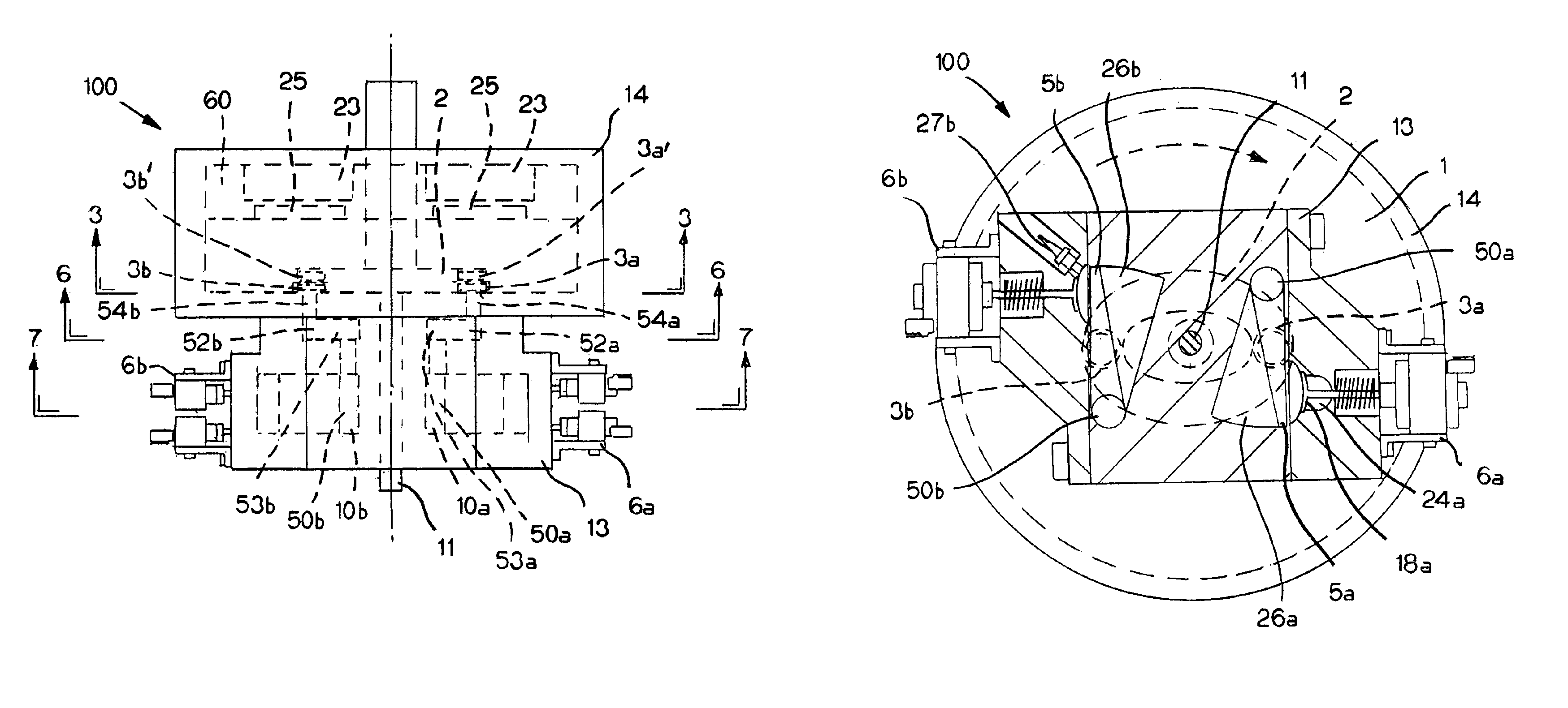
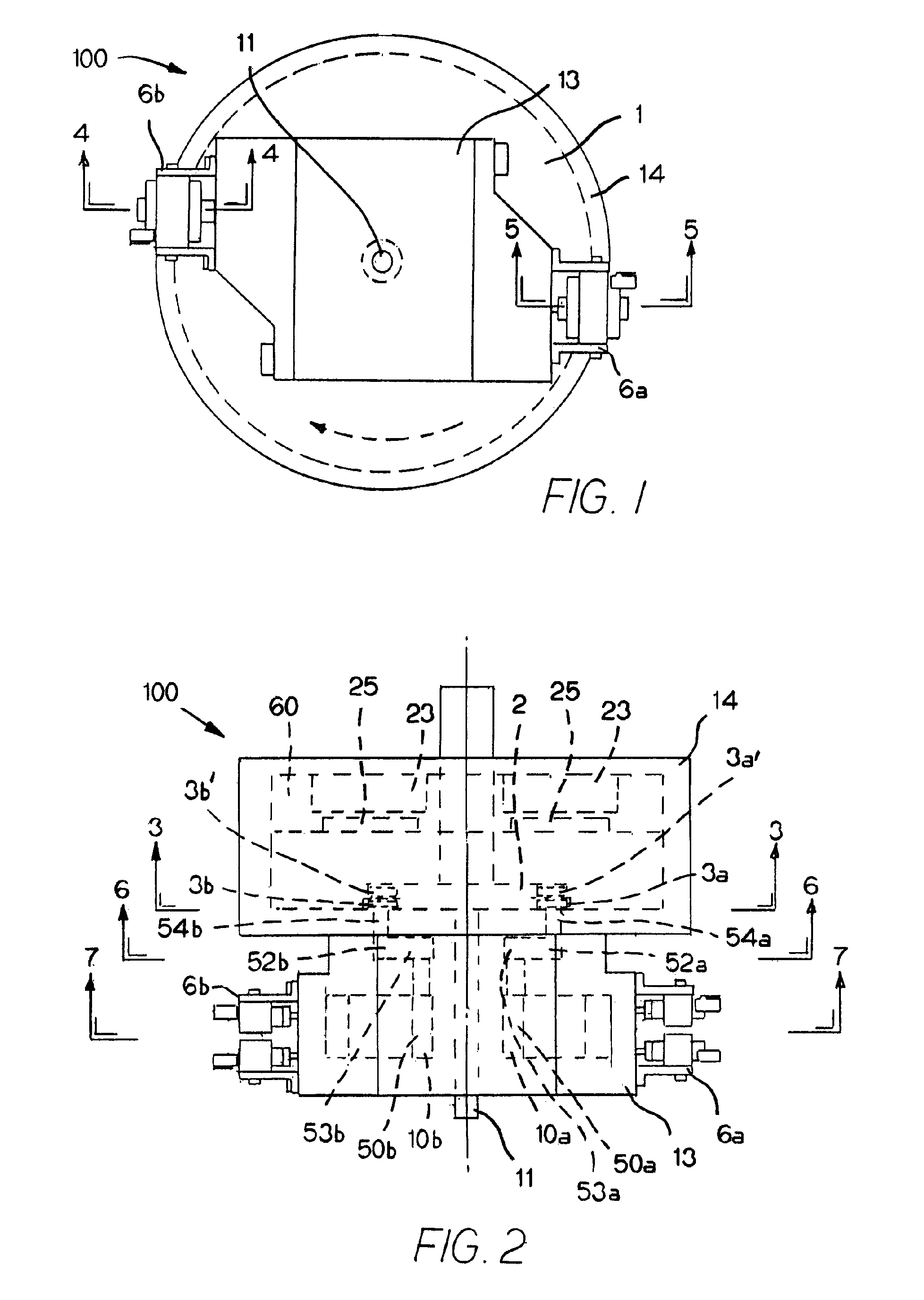
[0034]Referring first to FIGS. 1, 2, and 7, an exemplary internal combustion engine 100 made in accordance with the present invention includes a front housing (or engine block) 13 that defines two generally wedge-shaped combustion chambers 26a, 26b, although there could be fewer or more chambers without departing from the spirit and scope of the present invention. The exemplary internal combustion engine 100 further includes a second, rear housing 14 that defines an internal cavity 60 in which a wheel 1 is mounted for rotation. This wheel 1 is mounted on a crankshaft 11 that extends through both the front and rear housings 13, 14 of the engine 100 and is supported by a series of bearings (not shown).

[0035]Returning to the front housing 13, arranged inside each combustion chamber 26a, 26b is a gate 5a, 5b. As illustrated in FIG. 7, these gates 5a, 5b are also generally wedge-shaped, but become narrower as the respective combustion chamber 26a, 26b widens. In other words, the widest p...


PUM


Abstract

An internal combustion engine operates on a four-stroke cycle and includes a housing defining: one or more generally wedge-shaped combustion chambers, and an internal cavity in which a wheel is mounted for rotation on a crankshaft. Arranged inside each combustion chamber is a gate, with each gate having a corresponding gate control assembly including a control shaft. Each control shaft is supported by bearings that engage and ride in a generally elliptical cam-cutout defined in the surface of the wheel. Movement of the gate control assemblies within and with respect to the elliptical cam-cutout controls the movement and operation of the gates, such that, as the wheel rotates, a fuel / air mixture is drawn into a combustion chamber; compressed by the rotating movement of a gate; and ignited, imparting a force on the gate, with the gate then rotating to expel combustion gases through an exhaust port.

Description

CROSS-REFERENCE TO RELATED APPLICATIONS[0001]This application claims priority to U.S. Provisional Patent Application No. 60 / 779,338, filed Mar. 3, 2006, the entire disclosure of which is incorporated herein by reference.BACKGROUND OF THE INVENTION[0002]The present invention relates to internal combustion engines. In an internal combustion engine, the basic functionality includes: (1) the intake of a fuel-air mixture into a combustion chamber; (2) the compression of the fuel-air mixture; (3) the ignition of the fuel-air mixture; and (4) the expansion of the ignited mixture and exhausting of the combustion gases. The resultant release of energy in the form of expanding gas is used to power various mechanical devices, including vehicles.[0003]A reciprocating internal combustion engine is perhaps the most common form of internal combustion engine. In a reciprocating internal combustion engine, the reciprocating motion of a piston in a cylinder results in the compression of the fuel-air ...

Claims


Application Information

Patent Timeline
Patent Type & Authority Patents(United States)
IPC IPC(8): F02B53/00F02B57/00F02B57/08F02B75/26
CPCF01C9/002F01C21/0836F01C17/04
Inventor KARNES, MARK D.
Owner KARNES DYNO REV ENGINE
Why Eureka
Try Eureka