
Microfibrous entrapment of small reactive particulates and fibers for high contacting efficiency removal of contaminants from gaseous or liquid streams

a reactive particulate and microfibrous technology, which is applied in the direction of electrochemical generators, filtration separation, separation processes, etc., can solve the problems of limited useful life and performance attributes of filters, limited contact efficiency with liquid, gaseous or air streams, and low chemical conversation rates, etc., to achieve high activity and desirable selectivity, easy to fuse, and excellent performance

Active Publication Date: 2009-03-10
AUBURN UNIV
View PDF17 Cites 27 Cited by
  • Summary
  • Abstract
  • Description
  • Claims
  • Application Information

AI Technical Summary

Benefits of technology

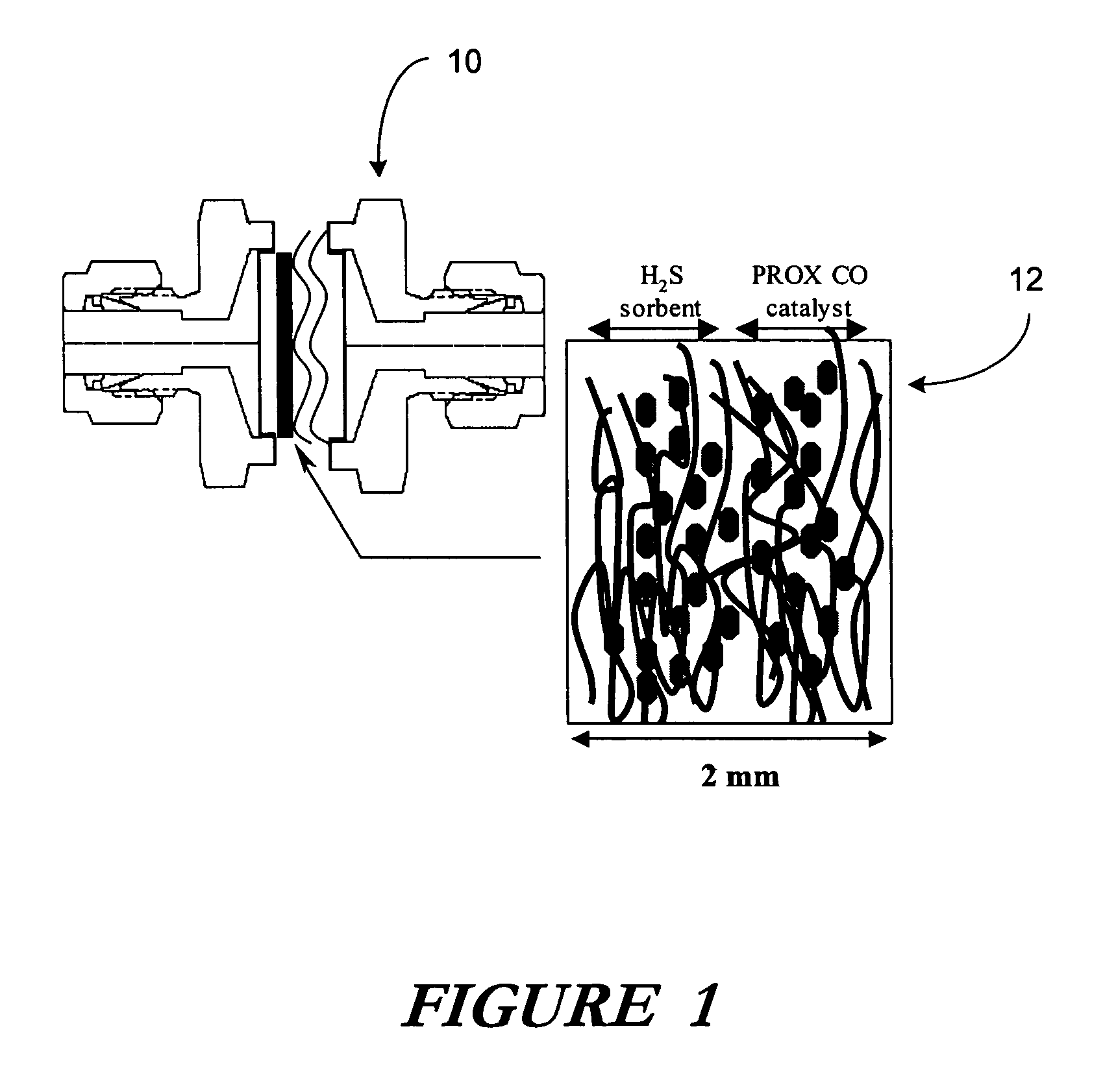
[0008]The present invention recognizes and addresses various of the foregoing limitations and drawbacks of chemically reactive heterogeneous contacting filtration, separation, and sorptive systems. Therefore, the present invention is directed to a microfibrous entrapped or coated reactive filtration system with entrapped particulates or fibers of a pre-defined reactive material for the high contacting efficiency removal of trace contaminants or harmful agents from liquid, gaseous or air streams. High contacting efficiency translates into smaller reaction vessels as well as multi-log reactant / contaminant reduction within the space of a few millimeters of microfibrous bed thickness.
[0009]It is, therefor, a principle object of the subject invention to provide a chemically-reactive filtration system for the removal of contaminants from liquid or gaseous streams. More particularly, it is an object of the present invention to provide a microfibrous filtration system with entrapped particulates or fibers of a pre-defined reactive material for the removal of contaminants from a liquid or gaseous stream. In such context, it is still a more particular object of the present invention to provide a multilayer microfibrous filtration system with entrapped particulates of predetermined reactive materials for the staged removal of numerous contaminants from a liquid, gaseous or air stream. Still further, it is an object of this invention to provide such a multilayer microfibrous filtration system in which physical entrapment of the reactant material within a microfibrous carrier matrix permits the reaction medium to operate in a variety of orientational, geometrical and vibrational environments without the traditional concerns for the influences of gravity, flow rate and fludization versus particle size or density based thermal convection.
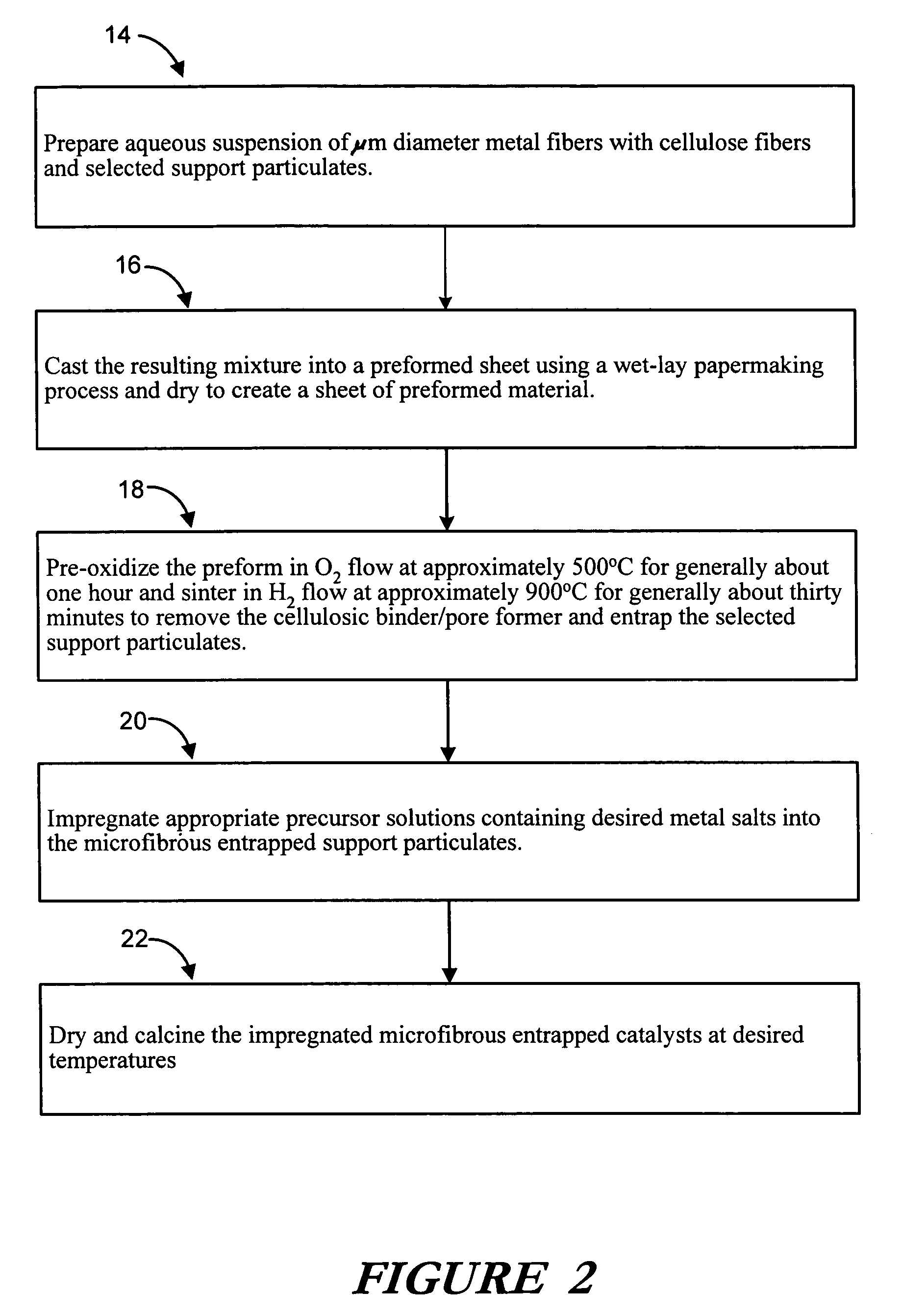
[0016]Traditional high speed and low cost paper making equipment and techniques may be used to prepare the composite material. In such a process, μm diameter metal, polymer, glass, or ceramic fibers in a variety of compositions and alloys may be slurried in an aqueous suspension (along with optional binders, if required) and with the possible use of cellulose fibers and other selected reactant or support particulates such as, but not limited to, alumina support particles. The resulting mixture may then be cast into a preformed sheet using a wet-lay process and dried to create a sheet of preformed material. Where a water soluble binder is used in this preparation, drying may be sufficient to fuse the fibers at their junctures, but in the case of those preforms utilizing cellulose, subsequent pre-oxidation in an O2 flow at approximately 500° C. for generally about one hour may be employed to remove the bulk of cellulose. Subsequent sintering of the preform in an H2 flow at an elevated temperature (approximately 900° C.) for generally about thirty minutes allows for removal of the remaining cellulosic binder / pore former and entraps the selected support particulates within a sinter-locked network of metal, glass or ceramic fibers.
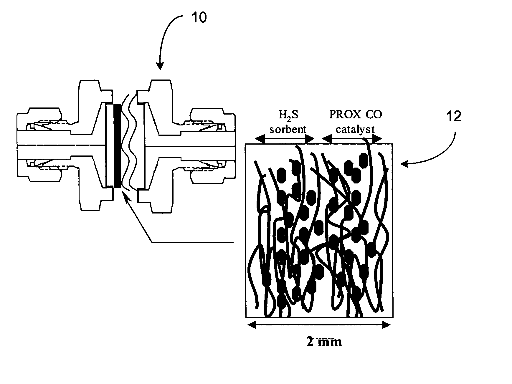
[0019]Reactive materials, such as ZnO, ZnO / Carbon or ZnO / SiO2 (e.g., H2S sorbents / reactants) or any combination of the three, may be placed onto the supports of at least one of these layers, as above described at loadings of between about 15 and 20 wt %. In particular, the ZnO / Carbon reactive material may provide excellent performance in removing H2S at low temperature PEM fuel cell stack temperatures (from 0 to 100 C) and thus may serve as a protective measure against exposure of the typically platinum anode and cathode catalysts against irreversible sulfur poisoning in the PEM fuel cell.
[0020]In a second layer of the multilayer structure a preferential catalytic oxidation CO (PROX CO) catalyst may be similarly impregnated onto the filtration layers support by the above described incipient wetness impregnation technique. Within such a layer, the support may be about a 150 micron diameter gamma alumina support entrapped within a sintered matrix of Ni, polymer, ceramic, glass or alloy fibers. The PROX CO catalyst may comprise cobalt promoted Pt / Al2O3. The high activity and desirable selectivity over a wide operating temperature range of such catalysts provides superior performance in reformate streams from between generally about 0° C. to generally about 200° C.

Problems solved by technology

While such methodologies were effective they suffered from numerous inefficiencies that limited the useful lives and performance attributes of the filters.
Limited contacting efficiency with the liquid, gaseous or air stream, low chemical conversation rates, limited heat and mass transfer through the filtration system, inability to regenerate, high weights, extremely limited duration of effectiveness, ineffectiveness at relatively low temperatures, and large pressure drops are among the numerous problems identified with prior art reactive filtration systems.

Method used


Image

  • Microfibrous entrapment of small reactive particulates and fibers for high contacting efficiency removal of contaminants from gaseous or liquid streams
  • Microfibrous entrapment of small reactive particulates and fibers for high contacting efficiency removal of contaminants from gaseous or liquid streams
  • Microfibrous entrapment of small reactive particulates and fibers for high contacting efficiency removal of contaminants from gaseous or liquid streams

Examples


examples

[0034]In one exemplary embodiment of the present invention in which the filtration reactor of the present invention is specifically designed for conversion of CO upstream of a PEM fuel cell, it can be seen that in the absence of Pt metal there exists no CO oxidizing activity at temperatures below 100° C. where a Co promoted Alumina support is used in the reactor. Even at temperatures above 250° C., CO conversion is only 40%. This is explained by the fact that Pt plays a crucial role in CO oxidation by providing the sites for CO adsorption and the Co promoter on alumina allows for more facile O2 adsorption. As a result, it can be seen that the present invention, including, but not limited to the present embodiment of a Co promoted Pt / Alumina catalyst within the microfibrous filtration mesh / reactor, provides an increased selective CO oxidation removal activity thus extending the life of any downstream PEM anode or cathode catalysts which are extremely sensitive to CO poisons.

[0035]Typ...


PUM

PropertyMeasurementUnit
thicknessaaaaaaaaaa
temperatureaaaaaaaaaa

Abstract

A microfibrous matrix with embedded supporting particulates / fibers and chemically reactive materials is provided as a filtration system for the removal of contaminants and other harmful agents from liquid and gaseous streams. Such materials may include chemically reactive materials as high surface area carbons, zeolites, silicas, aluminas, inorganic metal oxides, polymer resins, ZnO, ZnO / Carbon, Pt / γ-Al2O3, PtCo / γ-Al2O3, ZnO / SiO2 and various other catalysts, sorbents or reactants. The invention may be used to protect the intolerant anodes and cathodes of fuel cells from damaging H2S while simultaneously aiding the selective conversion of CO to CO2 in fuel streams predominated by hydrogen, to provide a highly efficient gas and / or liquid separation and purification methodology for gas masks, building filtration systems, and / or as polishing media located downstream of traditional packed bed filtration systems.

Description

CROSS-REFERENCE TO RELATED APPLICATIONS[0001]The present application claims priority to the Provisional U.S. Patent Application Ser. No. 60 / 498,255, filed on 26 Aug. 2003, and entitled “Microfibrous Entrapment of Small Reactive Particulates and Fibers for High Contacting Efficiency Removal of Contaminants from Gaseous or Liquid Streams.”STATEMENT REGARDING FEDERALLY-FUNDED RESEARCH[0002]The United States Government has a paid-up license in this invention and the right in limited circumstances to require the patent owner to license others on reasonable terms as provided for by the terms of Contract No. DASG-60-00-C-0070, awarded by the United States Army and administered through the U.S. Army Space & Missile Defense Command (SMDC) and Auburn University.FIELD OF THE INVENTION[0003]The present invention generally relates to sorbents, catalysts and filters for the removal of contaminants and toxins from liquid, gaseous, and air streams. In particular, the present invention relates to a ...

Claims


Application Information

Patent Timeline
Patent Type & Authority Patents(United States)
IPC IPC(8): B01D53/02B01D29/07B01D53/34B01D53/52B01D53/86C01B3/50C01B3/58
CPCB01D53/02B01D53/52B01D53/8612B01D53/864B01D53/885C01B3/508C01B3/583H01M8/0675B01D2257/304B01D2257/502B01D2258/0208B01D2258/0225C01B2203/042C01B2203/044C01B2203/047C01B2203/0485C01B2203/066H01M8/0668Y02E60/50
Inventor TATARCHUK, BRUCE J.CHANG, BONG KYULU, YONGCHEN, LAIYUANLUNA, ERICCAHELA, DON
Owner AUBURN UNIV
Learn More