Solar distillation loop evaporation sleeve

a solar distillation loop and evaporation sleeve technology, which is applied in vacuum distillation separation, vessel construction, separation processes, etc., can solve the problems of high energy/conveyance costs and unacceptable water quality, and achieve the effect of increasing the amount of evaporated water produced by the apparatus, improving the operation of the solar distillation loop apparatus, and increasing the water evaporation area

Inactive Publication Date: 2009-03-10
U S A AS REPRESENTED BY THE SEC OF THE DEPT OF THE INTERIOR
View PDF17 Cites 7 Cited by
  • Summary
  • Abstract
  • Description
  • Claims
  • Application Information

AI Technical Summary

Benefits of technology

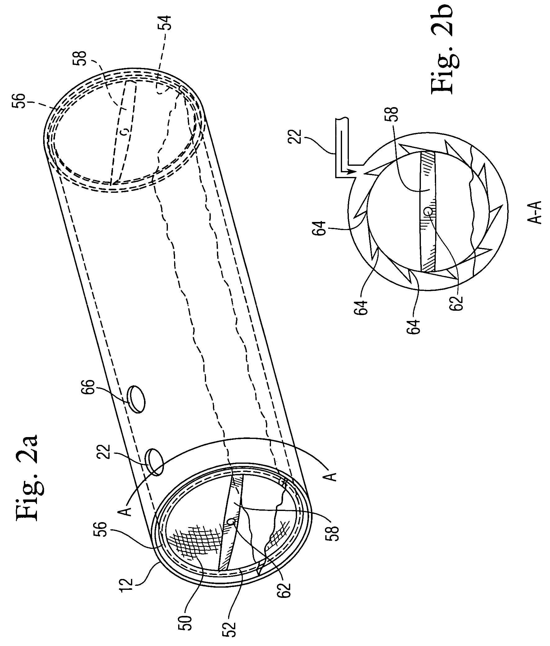
[0012]The invention proposed herein comprises a device to improve the operation of a solar distillation loop apparatus. The device is an evaporation sleeve placed within the solar distillation loop apparatus that increases the water evaporation area. By increasing the water evaporation area within the apparatus, the amount of evaporated water produced by the apparatus is increased.

Problems solved by technology

These problems related to unacceptable water quality of many water sources in these regions and high energy / conveyance costs to use these water sources for irrigation or other purposes within these regions.

Method used


Image

  • Solar distillation loop evaporation sleeve
  • Solar distillation loop evaporation sleeve
  • Solar distillation loop evaporation sleeve

Examples


Embodiment Construction

[0021]The invention, as embodied herein, comprises an evaporation sleeve that is placed within a solar distillation loop apparatus to increase the amount of water evaporated by the apparatus. The evaporation sleeve significantly increases the water surface area available within the solar distillation loop.

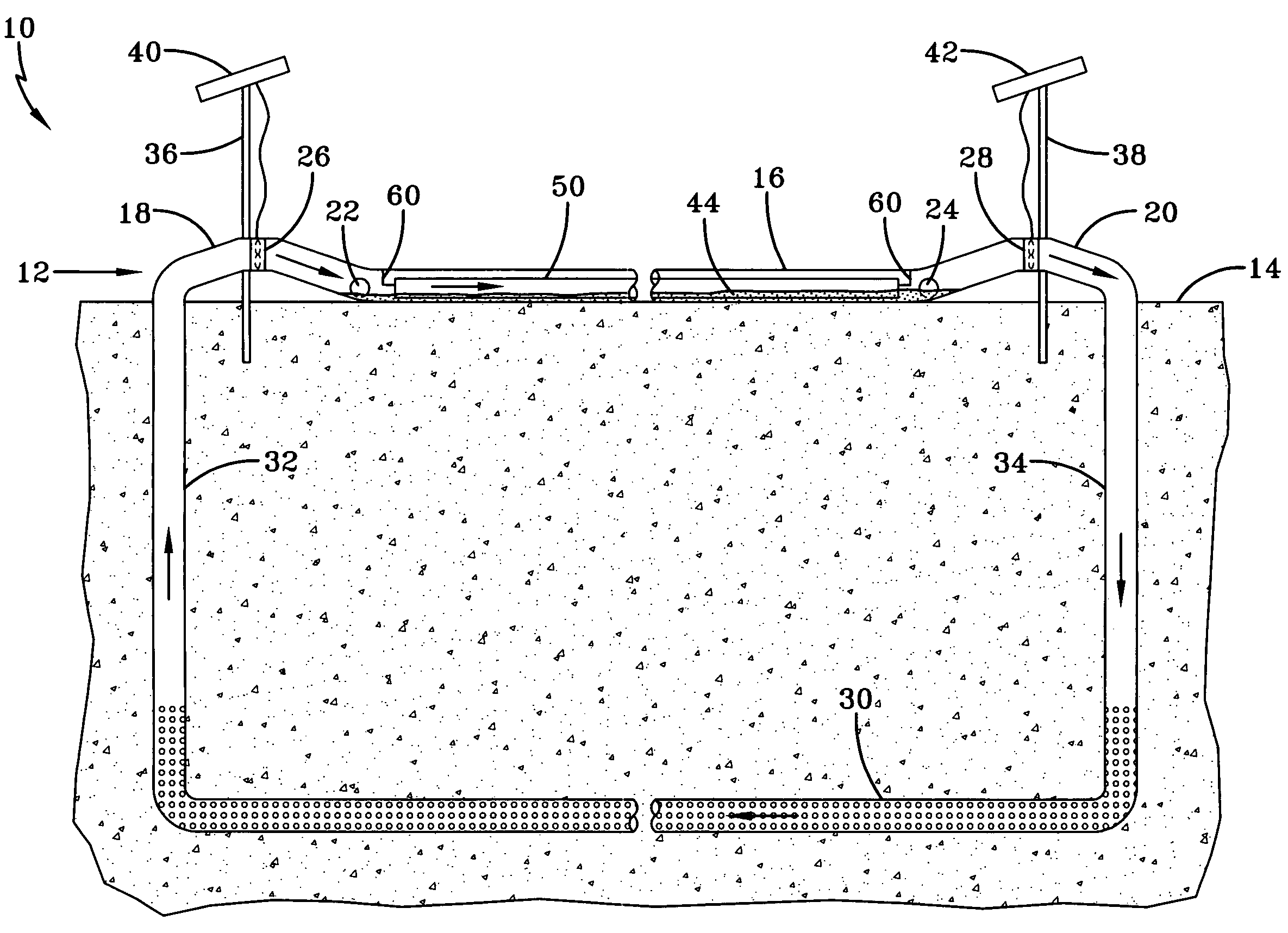
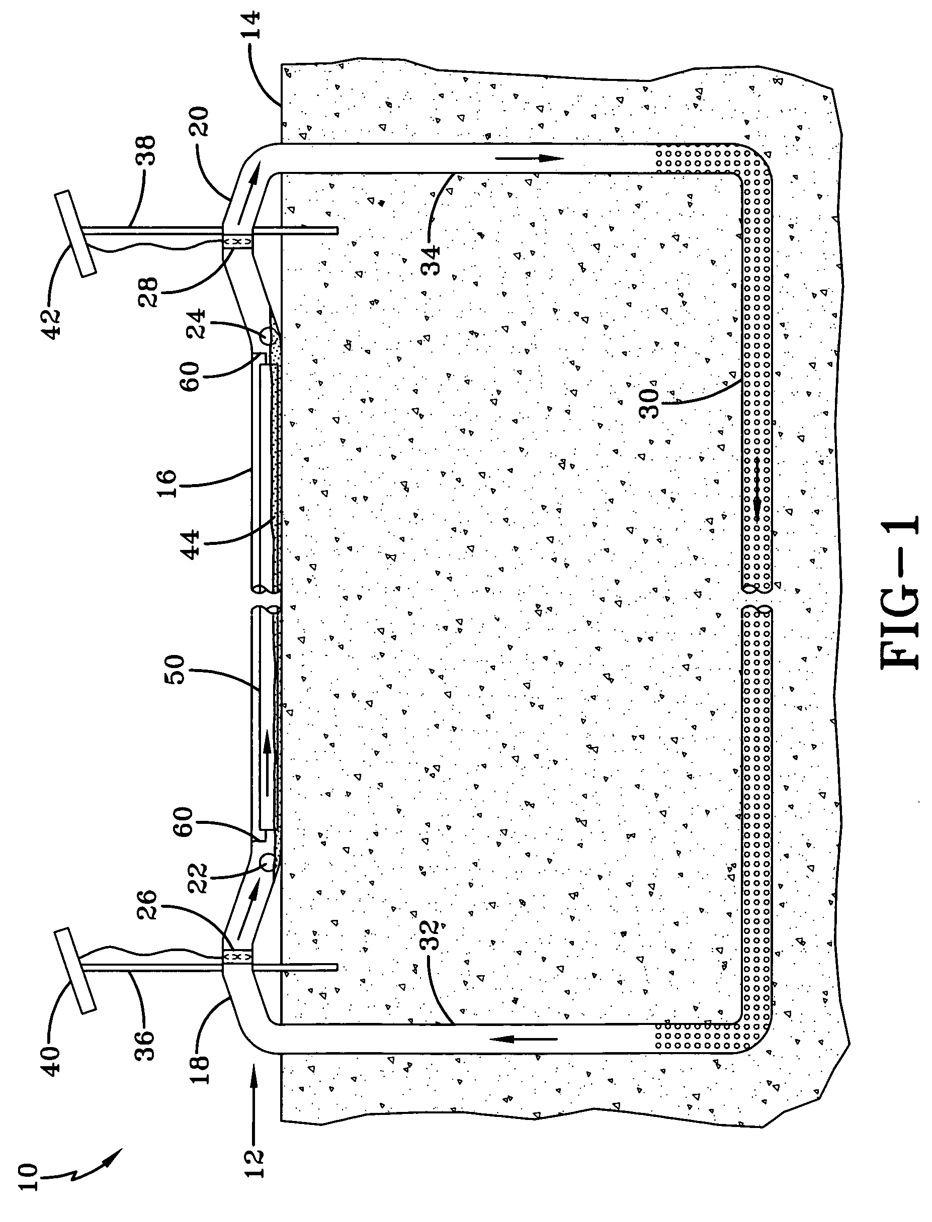
[0022]The operation of a solar distillation loop apparatus is described in detail in application Ser. No. 10 / 729,265, filed on Dec. 3, 2003. Referring to FIG. 1, the general operation is as follows. Loop 10 comprises a first pipe section 12 disposed on the ground surface 14. The first pipe section 12 includes a substantially straight portion 16 and elevated portions 18, 20 on each end of the substantially straight portion 16. An impure water inflow coupling 22 is located at one end of the straight portion 16 and an impure water outflow coupling 24 is located at the other end of the straight portion. Solar powered fans 26, 28 are disposed in each of the elevated portions 18, 20 of t...


PUM

PropertyMeasurementUnit
depthaaaaaaaaaa
diameteraaaaaaaaaa
surface areaaaaaaaaaaa

Abstract

An evaporation sleeve is placed within a solar distillation loop apparatus to increase the amount of water evaporated by the apparatus. The evaporation sleeve is rotationally attached within the above ground portion of the solar distillation loop so the sleeve lifts impure water into the air flow within the system. The evaporation sleeve significantly increases the water surface area available to the air flow within a solar distillation loop.

Description

CROSS-REFERENCE TO RELATED APPLICATION(S)[0001]The present application is a continuation-in-part of U.S. patent application Ser. No. 10 / 729,265, now U.S. Pat. No. 7,108,769 entitled “SOLAR DISTILLATION LOOP” filed on Dec. 3, 2003, which is incorporated by reference herein.STATEMENT OF GOVERNMENT INTEREST[0002]The invention described herein may be manufactured and used by or for the Government of the United States of America for governmental purposes without payment of any royalties thereon or therefor.BACKGROUND OF THE INVENTION[0003]1. Field of the Invention[0004]This invention relates in general to providing water in semi-arid and arid regions, more particularly to providing purified water from impaired water sources in semi-arid and arid regions, and most particularly to providing purified water from impaired water sources in semi-arid and arid regions through solar distillation.[0005]2. Description of the Related Art[0006]In previously filed application Ser. No. 10 / 729,265 for a...

Claims


Application Information

Patent Timeline
Patent Type & Authority Patents(United States)
IPC IPC(8): B01D3/04C02F1/14
CPCB01D1/0035B01D3/346B01D5/006C02F1/14E03B3/28Y10S203/01Y10S159/903Y02W10/37Y02A20/212Y02A20/00
Inventor CONSTANTZ, JAMES EDWARD
Owner U S A AS REPRESENTED BY THE SEC OF THE DEPT OF THE INTERIOR
Why Eureka
Try Eureka