Low energy electron cooling system and method for increasing the phase space intensity and overall intensity of low energy ion beams
What is AI technical title?
AI technical title is built by Patsnap AI team. It summarizes the technical point description of the patent document.
a low energy electron cooling and phase space intensity technology, applied in the field of particle beam physics devices, can solve the problems of electron beam imperfections being transferred to the electron beam, ion beam initiation energy is very low by particle beam standards, and the electron beam produces much more energy, so as to improve the achievable intensity and beam quality, optimize the effect of end-product production and large current in the electron beam
Active Publication Date: 2009-03-10
LARSON DELBERT J
View PDF6 Cites 12 Cited by
Summary
Abstract
Description
Claims
Application Information
AI Technical Summary
This helps you quickly interpret patents by identifying the three key elements:
Problems solved by technology
Method used
Benefits of technology
Benefits of technology
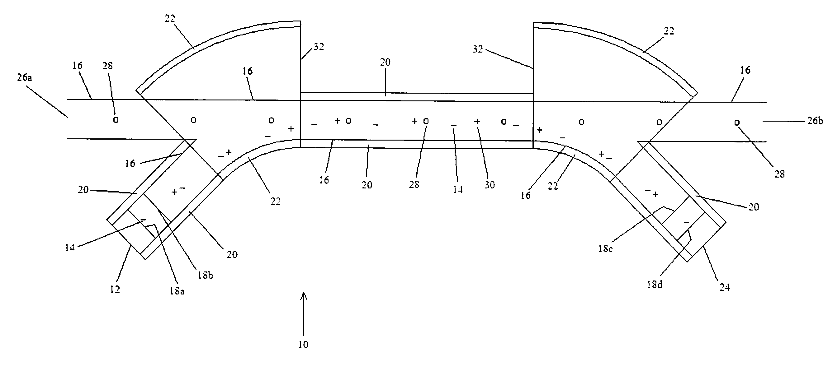
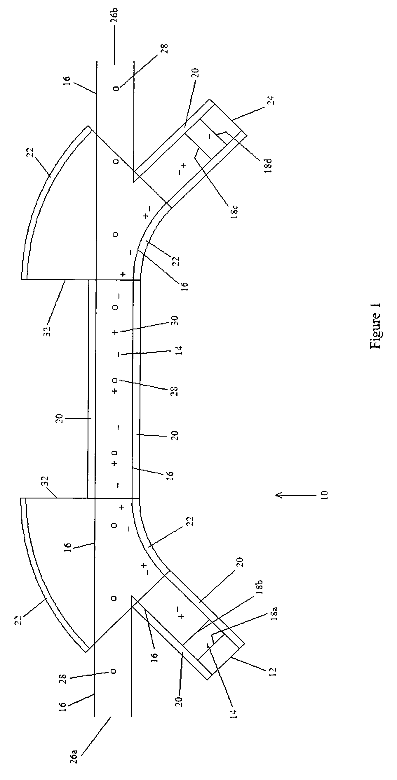
[0020]Distinctly, the present invention employs a cathode-side electrode biased positively with respect to the final cathode-side electrode and also employs a collector-side electrode biased positively with respect to the initial collector-side electrode. (Optionally, additional electrodes can be used on the cathode-side and collector-side as well. The final cathode-side electrode and initial collector-side electrode are each biased at the potential of the overlap region of the vacuum chamber within which the electron beam and ion beam overlap.) The presence of electrodes biased in this way enables an electric field which results in a force on the electrons that is directed away from the region where the beams overlap. Since the force on positively charged ions is in the opposite direction as the force on negatively charged electrons, the positively charged (non-beam) neutralizing-background-ions will be trapped longitudinally within the overlap region. The neutralizing-background-ions will also be trapped transversely by the solenoidal and torroidal magnetic guide fields. Hence, the neutralizing-background-ions are effectively trapped within the region that the electron and ion beams overlap. Since the trapped neutralizing-background-ions have positive charge, while the electrons have negative charge, the presence of the trapped neutralizing-background-ions will substantially offset the electron beam self space charge, enabling substantially larger currents in the electron beam.
[0021]The electron cooling system includes an electron injector which injects an electron beam into the storage ring, onto the path of a particle beam, and an electron collector which captures the electron beam. The electrons are injected with a predetermined amount of energy to cause the particles in the particle beam to move at an ideal velocity. By traveling and interacting with the particle beam, the electron beam maintains the particle beam within parameters that optimizes end-product production. Any heating, scattering and even deceleration that would otherwise adversely affect the particles in the particle beam is effectively compensated for by the electron beam. Accordingly, scattering and energy loss in the particle beam is substantially continuously compensated for before significant instabilities have an opportunity to develop. In this manner, events that would typically cause significant instabilities in the particle beam are minimized if not eliminated.
[0022]Since the effectiveness of the correction of particle beam errors is proportional to the electron current in the overlapping electron beam, the present invention will result in a large improvement in the achievable intensity and beam quality of low energy particle beams. By enabling higher intensity and beam quality of low energy particle beams, the present invention will also lead to improvement in the yields of photons, neutrons, nuclear isotopes and fusion energy produced by the low energy particle beams.
Problems solved by technology
Several nuclear reactions are known to produce much more energy than the energy required to initiate the interaction, and the initiation energy is very low by particle beam standards.
Particle collisions between the two beams result in ion beam imperfections being transferred to the electron beam.
However, the conventional technique has serious difficulty for low energy situations.
Conventional electron beams have an intensity that is limited by the electron beam's self space charge, and this limit is severe for low energy electron beams.
Method used
Image
Click on the blue label to locate the original text in one second.
Reading with bidirectional positioning of images and text.
Examples
Embodiment Construction
[0028]An electron cooling system 10 for increasing the phase space intensity and overall intensity of low energy particle beams is shown in FIG. 1. The electron cooling system 10 utilizes a combination of elements, including the electron supply device such as an electron cathode 12 for supplying a beam of electrons 14, a vacuum chamber 16 for containing particles, electrodes 18 to provide electric fields to accelerate or decelerate the electron beam and which serve to trap neutralizing-background-ions, solenoidal 20 and torroidal 22 wire windings to provide guiding and containing magnetic fields, an electron collector including a collection plate 24 having a material surface to collect the electrons 14 after they have performed their function, and ports 26 to allow beam particles 28 to enter and leave the electron cooling system 10. Positive neutralizing-background-ions 30, trapped by the fields of the electrodes 18, solenoids 20, and torroids 32 are also shown in FIG. 1.
[0029]The e...
PUM
Abstract
A low energy electron cooling system and method for increasing the phase space intensity and overall intensity of low energy ion beams, including a vacuum chamber to allow electron beam and ion beam merging and separation, a cathode to generate the electron beam, a collector to collect the electron beam, magnetic field generation devices to guide the electrons on their desired trajectories, and electrodes to accelerate and decelerate the electron beam. By overlapping the electron and ion beams, thermal energy is transferred from the ion beam to the electron beam, which allows an increase in the phase space density and overall density of the ion beams. Advantageously, the low energy electron cooling system uses electrodes to set up electrostatic potentials that trap non-beam neutralizing-background-ions longitudinally within the electron cooling region and solenoidal fields that trap the non-beam neutralizing-background-ions radially within the electron cooling region. The trapped non-beam neutralizing-background-ions allow electron cooling currents that are vastly larger than the space charge limit of previous electron cooling devices, which leads to vastly improved functioning of the electron cooling device over previous electron cooling devices.
Description
REFERENCES CITED [REFERENCED BY][0001]The following references are incorporated by reference in their entirety.U.S. Patent Documents[0002]U.S. Pat. No. 5,854,531 December 1999 Young, et al.[0003]U.S. Pat. No. 5,138,271 August 1992 Ikegami[0004]U.S. Pat. No. 5,001,438 March 1991 Miyata et al.[0005]U.S. Pat. No. 4,867,939 Sep. 19, 1989 DeutchOther Documents[0006]G. I. Budker, The 1966 Proc. Int. Symp. Electron and Positron Storage Rings, Saclay, Atomnaya Energiya vol. 22 p. 346, 1967.[0007]L. Spitzer, “Physics of Fully Ionized Gases”, (New York: Interscience, 1956) pp. 80-81.[0008]G. I. Budker, et al., Particle Accelerators, Vol. 7, 197-211 (1976).[0009]M. Bell, et al., Physics Letters, Vol. 87B, No. 3, (1979).[0010]T. Ellison, et al., IEEE Trans. Nuc. Sci., Vol. NS-30, No. 4, 2636-2638, (1983).[0011]D. J. Larson, et al., “Operation of a prototype intermediate-energy electron cooler”, NIM, A311, 30-33 (1992).FIELD OF THE INVENTION[0012]The present invention relates to particle beam ph...
Claims
Application Information
Patent Timeline
Application Date:The date an application was filed.
Publication Date:The date a patent or application was officially published.
First Publication Date:The earliest publication date of a patent with the same application number.
Issue Date:Publication date of the patent grant document.
PCT Entry Date:The Entry date of PCT National Phase.
Estimated Expiry Date:The statutory expiry date of a patent right according to the Patent Law, and it is the longest term of protection that the patent right can achieve without the termination of the patent right due to other reasons(Term extension factor has been taken into account ).
Invalid Date:Actual expiry date is based on effective date or publication date of legal transaction data of invalid patent.

