Broadcast receiver receiving broadcasts utilizing variable directional antenna

a receiver and variable directional technology, applied in the field of broadcast receivers, can solve the problems of inability to easily modify the directivity of the receiver once installed, the conventional receiver utilizing the variable directional antenna has failed to account for the measures related to channel search, and the conventional receiver utilizing the variable directional antenna has failed to realize the effect of channel search

Inactive Publication Date: 2009-03-10
FUNAI ELECTRIC CO LTD
View PDF4 Cites 18 Cited by
  • Summary
  • Abstract
  • Description
  • Claims
  • Application Information

AI Technical Summary

Benefits of technology

[0013]In view of the foregoing, an object of the present invention is to allow channel search to be conducted efficiently in a broadcast receiver utilizing a variable directional antenna.
[0020]In accordance with the present invention, when the first condition is established, or in accordance with another aspect, determination is made as to whether reception is allowed or not for only a channel that was previously identified as invalid for reception in the channel search. Accordingly, the time required for channel search becomes shorter as compared to the case where determination of valid / invalid reception is made for all the channels, and identification can be made as to whether there is a new channel valid for reception. Therefore, channel search can be conducted efficiently in a broadcast receiver utilizing a variable directional antenna.
[0021]In accordance with the present invention, determination is made as to whether reception is valid or invalid for a channel that was previously identified as valid for reception, starting sequentially from the direction previously identified as being valid for reception by the variable directional antenna. Accordingly, channel search can be conducted efficiently since the channel previously identified as valid for reception can be confirmed.
[0022]In accordance with the present invention, determination is made as to whether reception is valid or invalid for a channel that was previously identified as being valid for reception, starting sequentially from a direction differing from the direction previously identified as being valid for reception by the variable directional antenna. Accordingly, channel search can be conducted efficiently since the channel previously identified as being valid for reception can be confirmed, corresponding to transfer of the location of a broadcast station that outputs broadcast waves.

Problems solved by technology

Since the antenna is generally installed at the roof or the like of a building in a fixed manner, the directivity cannot be readily modified when once installed.
Channel search utilizing a variable directional antenna is generally time consuming.
However, conventional receivers utilizing variable directional antennas have failed to account for measures related to channel search.

Method used


Image

  • Broadcast receiver receiving broadcasts utilizing variable directional antenna
  • Broadcast receiver receiving broadcasts utilizing variable directional antenna
  • Broadcast receiver receiving broadcasts utilizing variable directional antenna

Examples


Embodiment Construction

[0034]An embodiment of a broadcast receiver of the present invention will be described in detail hereinafter with reference to the drawings. In the drawings, the same or corresponding elements have the same reference character allotted, and description thereof will not be repeated.

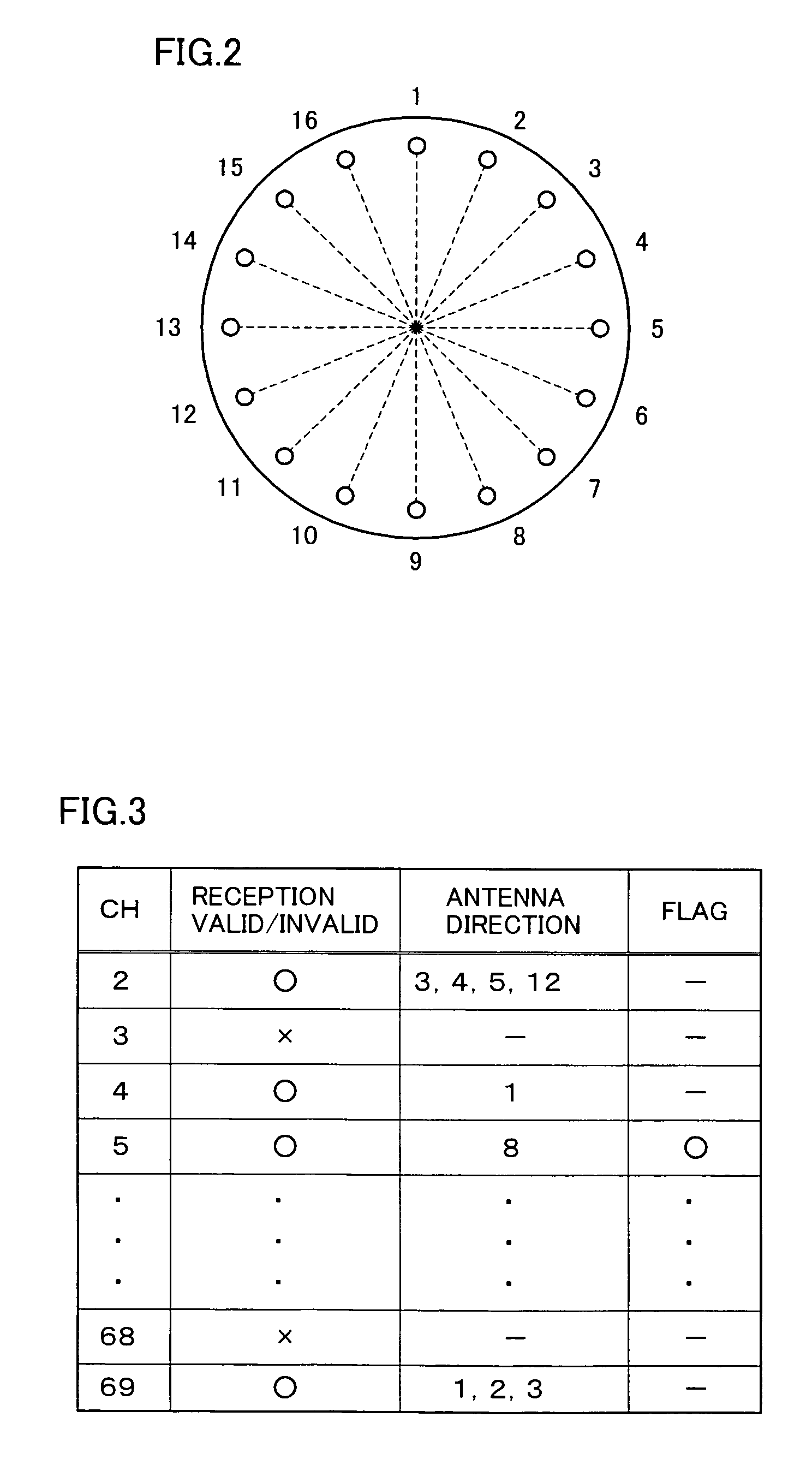
[0035]Although a smart antenna is employed as the antenna receiving a broadcast signal in the present embodiment, the variable directional antenna of the present invention is not limited thereto. Any antenna capable of switching its directivity can be employed in the present invention.

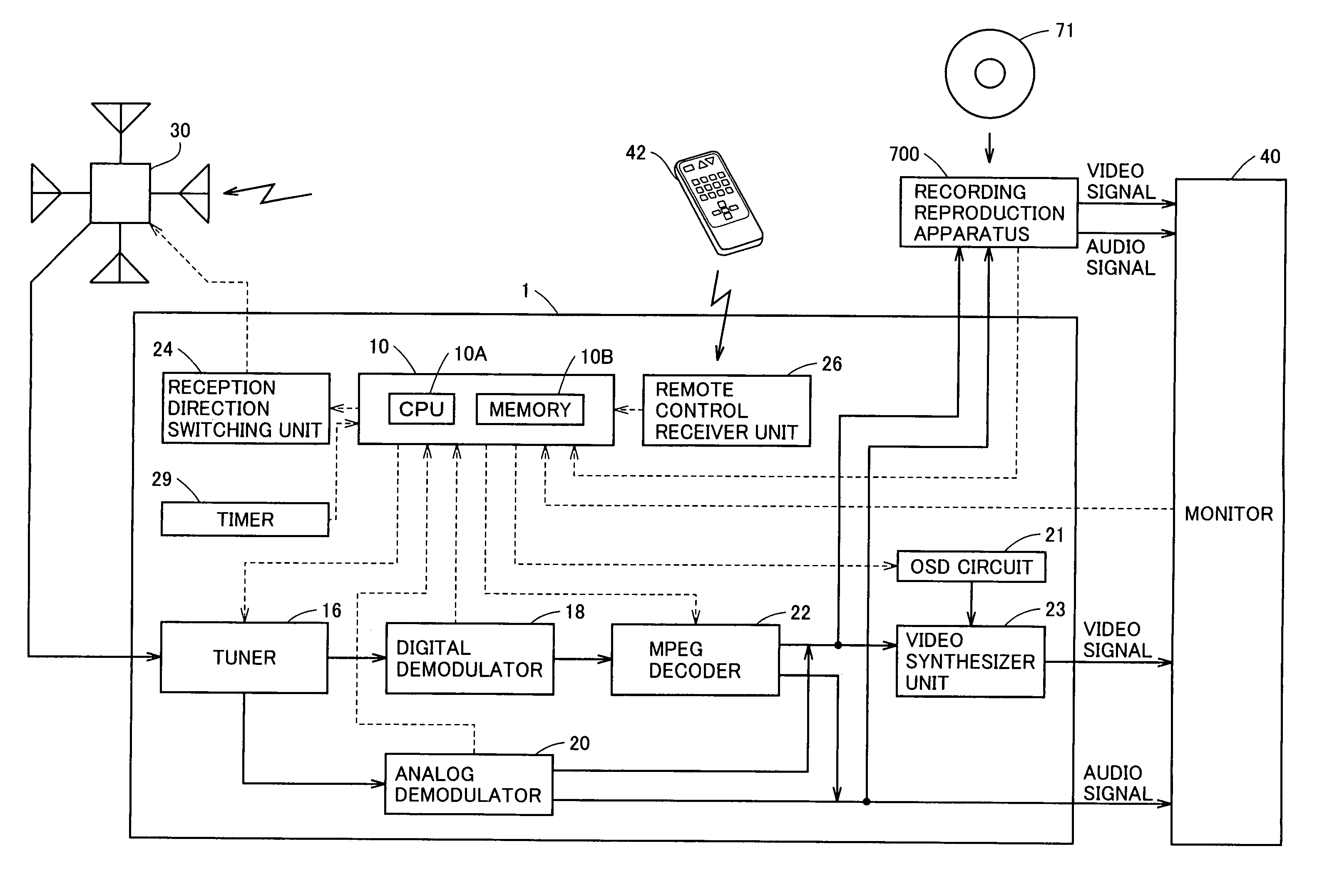
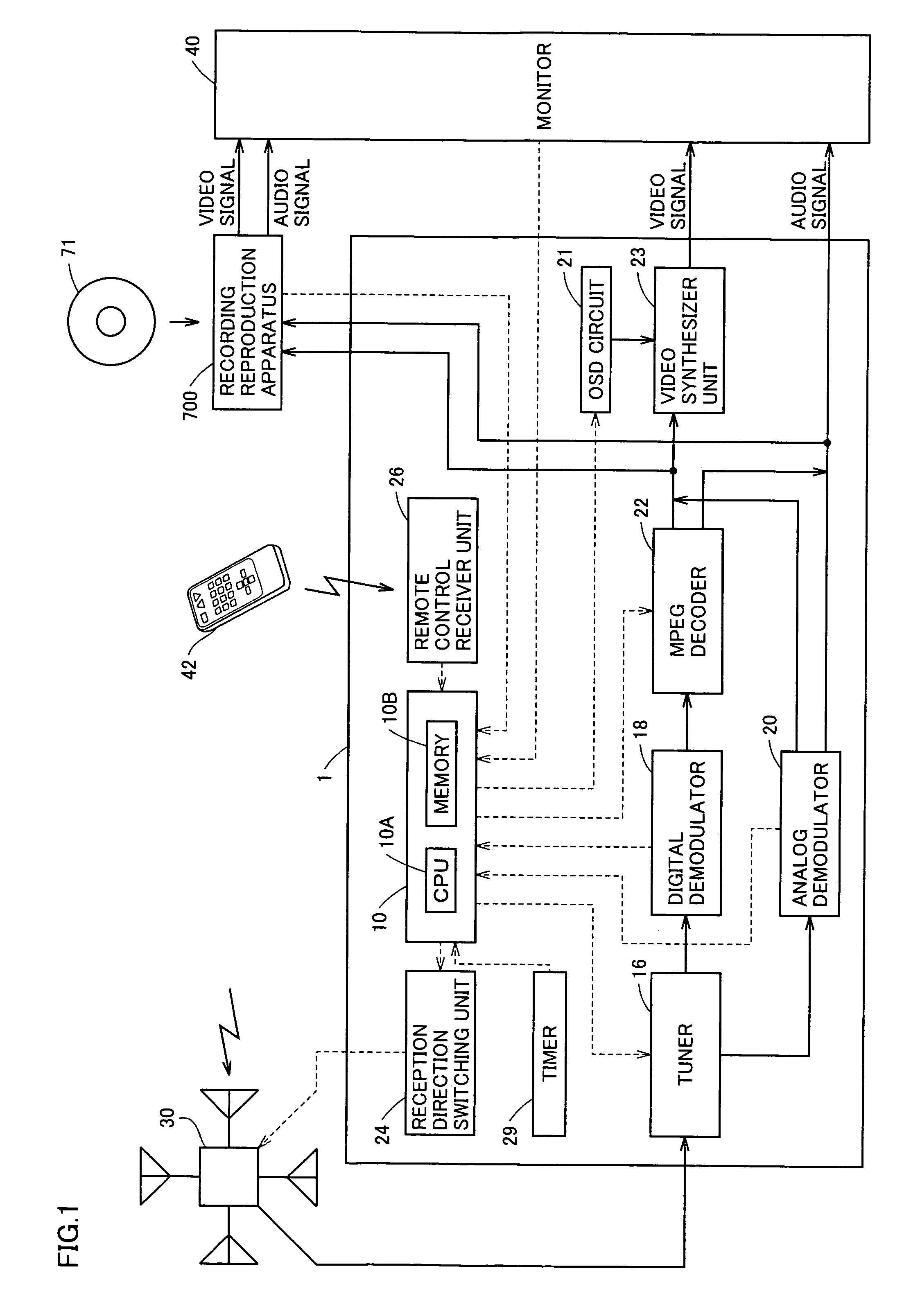
[0036]Referring to FIG. 1, a broadcast receiver 1 is connected to a smart antenna 30 to receive broadcast signals utilizing smart antenna 30, and outputs a reception direction switching signal to smart antenna 30. Broadcast receiver 1 also outputs video signals and audio signals to a monitor 40. Broadcast receiver 1 also receives an instruction signal from a remote controller 42.

[0037]Smart antenna 30 is formed of a plurality...


PUM


Abstract

In a broadcast receiver, determination is made, as channel search, whether a broadcast wave is valid for reception for all reception directions by a variable directional antenna with respect to only the frequency having the information stored as being invalid for reception in a storage unit.

Description

BACKGROUND OF THE INVENTION[0001]1. Field of the Invention[0002]The present invention relates to broadcast receivers, particularly a broadcast receiver that can receive broadcasts utilizing a variable directional antenna.[0003]2. Description of the Related Art[0004]Television broadcasting has the frequency band of VHF (Very High Frequency) and UHF (Ultra High Frequency) allotted. In general, the Yagi antenna is employed for receiving television broadcast signals. The Yagi antenna is constituted of a reflector, a radiator, and a director, and has high directivity towards the director side by the function of the reflector. The merit of large gain is also recognized in the Yagi antenna.[0005]The Yagi antenna is set to have its directivity match the direction of the broadcast station in order to obtain favorable reception. A receiver employing such an antenna carries out the process of searching for a channel valid for reception by that receiver. This process is called “channel search”....

Claims


Application Information

Patent Timeline
Patent Type & Authority Patents(United States)
IPC IPC(8): H04B7/14H03J5/02H04B1/16H04B1/18H04N5/44
CPCH01Q25/002H04H20/106H04H20/26H04H60/41
Inventor SUZU, HIROKAZU
Owner FUNAI ELECTRIC CO LTD
Why Eureka
Try Eureka