Muffler

a technology of muffler and muffler body, which is applied in the field of muffler, can solve the problems of large pressure loss, unsatisfactory muffle exhaust noise, etc., and achieves the effect of reducing flow noise, exhaust noise, exhaust noise, vehicle noise, and cabin noise, and minimizing pressure loss

Inactive Publication Date: 2009-03-17
CALSONIC KANSEI CORP
View PDF30 Cites 10 Cited by
  • Summary
  • Abstract
  • Description
  • Claims
  • Application Information

AI Technical Summary

Benefits of technology

[0008]According to the present invention, a muffler capable of sufficiently reducing flow noise, exhaust noise, vehicle noise, and cabin noise, minimizing a pressure loss, and improving output power is provided.

Problems solved by technology

This results in insufficiently reducing the kinetic energy of the exhaust gas flow, to unsatisfactorily muffle flow noise, exhaust noise, vehicle noise, and cabin noise.
This results in causing a large pressure loss (deteriorating a pressure loss level) and lowering output power.

Method used


Image

  • Muffler
  • Muffler
  • Muffler

Examples


first embodiment

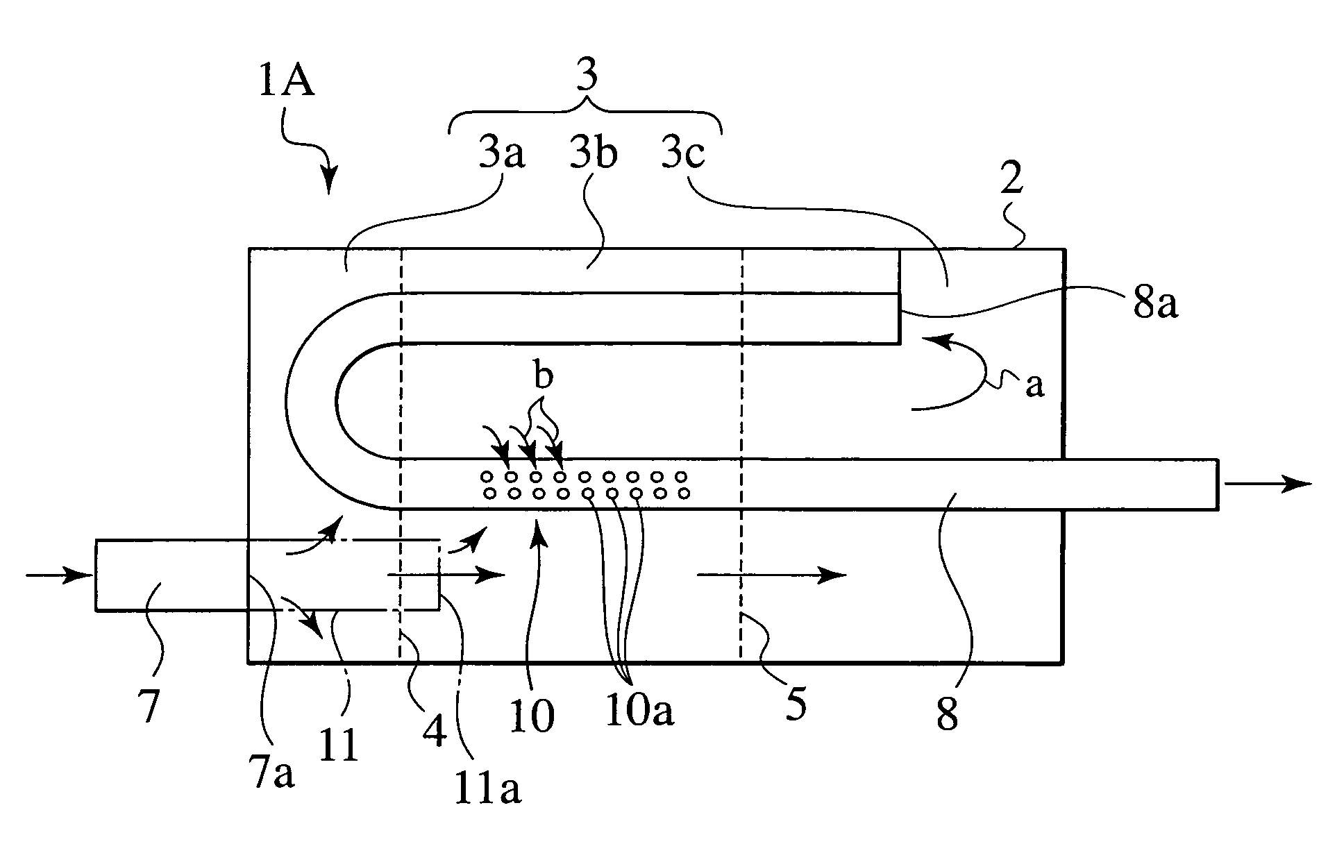
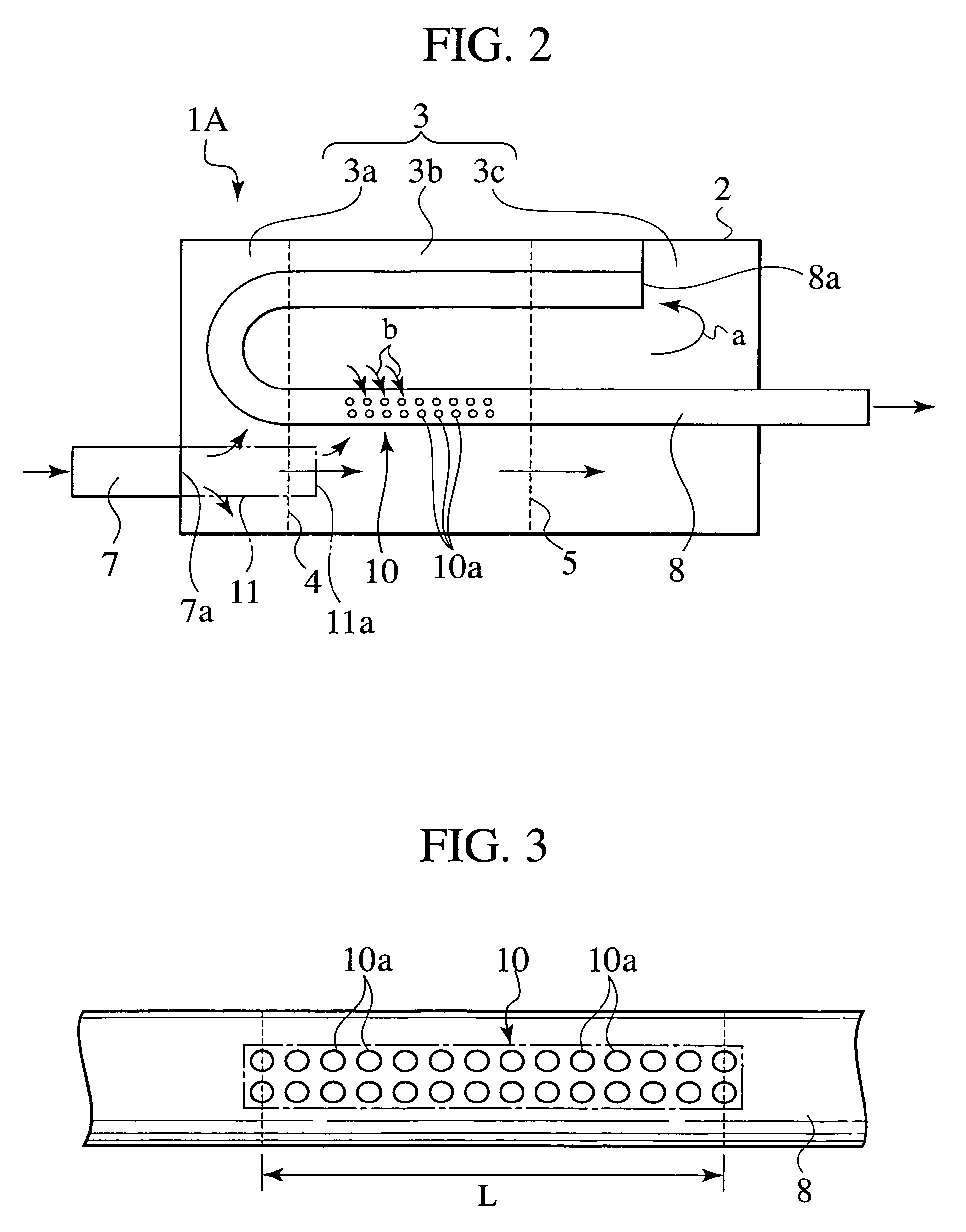
[0019]FIGS. 2 to 5 show a muffler according to the first embodiment of the present invention. In FIG. 2, the muffler 1A has a muffler body 2 as a casing defining a substantially closed space. The muffler body 2 forms an expansion room 3. The expansion room 3 is partitioned with two baffle plates 4 and 5 into first to third expansion chambers 3a, 3b, and 3c. The first expansion chamber 3a forms a first acoustic structure that is connected to a second acoustic structure formed of the second expansion chamber 3b with the baffle plate 4 serving as an acoustic resistive element being provided between the first and second expansion chambers 3a and 3b. The second acoustic structure is connected to a third acoustic structure formed of the third expansion chamber 3c with the baffle plate 5 serving as an acoustic resistive element being provided between the second and third expansion chambers 3b and 3c.

[0020]The first expansion chamber 3a has an opening for passing an end 7a of an upstream p...

second embodiment

[0030]FIGS. 6 and 7 show a muffler according to the second embodiment of the present invention. FIG. 6 is a schematic view showing the muffler and FIG. 7 is an enlarged view showing an opening 10 formed on a downstream pipe of the muffler.

[0031]In FIGS. 6 and 7, the muffler 1B according to the second embodiment has an opening 10 made of a slit 10b extending in an axial direction of the downstream pipe 8. The other arrangements of the second embodiment are the same as those of the first embodiment, and therefore, will not be explained in detail. The muffler 1B of the second embodiment provides the same operation and effect as those of the first embodiment.

[0032]According to the second embodiment, the slit 10b has an elongate shape extending in the axial direction of the downstream pipe 8 and a position thereof changes acoustic boundary conditions to decrease the order components of discharge noise. It is preferable, therefore, to select the position of the slit 10b according to acous...


PUM


Abstract

A muffler is capable of sufficiently reducing flow noise, discharge noise, vehicle noise, and cabin noise, preventing a pressure loss, and improving output power. The muffler has a muffler body, an upstream pipe that opens in the muffler body, and a downstream pipe that opens in the muffler body. An opening is formed in a side wall of the downstream pipe in the muffler body. The opening consists of many small holes arranged in an elongated area extending in an axial direction of the downstream pipe.

Description

BACKGROUND OF THE INVENTION[0001]1. Field of the Invention[0002]The present invention relates to a muffler arranged in an exhaust path for reducing exhaust noise.[0003]2. Description of the Related Art[0004]FIG. 1 shows a muffler according to a related art. In the muffler 50, exhaust gas passes through an upstream pipe 54 and enters a first chamber 51 through small holes 54a. Also, the exhaust gas exits from an outlet end of the upstream pipe 54 and enters a second chamber 52. The exhaust gas in the first chamber 51 enters a downstream pipe 55 through an inlet end thereof. The exhaust gas in the second chamber 52 enters the downstream pipe 55 through small holes 55a of the downstream pipe 55. The exhaust gas is then discharged into the atmosphere. According to the flow of exhaust gas mentioned above, noise from an engine passes through the upstream pipe 54 and enters the muffler 50. The noise expands when the exhaust gas enters the first chamber 51 through the small holes 54a and co...

Claims


Application Information

Patent Timeline
Patent Type & Authority Patents(United States)
IPC IPC(8): F01N1/06F01N1/00F01N1/08
CPCF01N1/003F01N1/06F01N1/08F01N2210/00F01N2260/16F01N2270/06F01N2470/04F01N2490/08
Inventor TOYOSHIMA, YOUHEI
Owner CALSONIC KANSEI CORP
Why Eureka
Try Eureka