Connecting member and connector each having a slider adapted to displace contact portions

a technology of connecting member and connector, which is applied in the direction of coupling device connection, optics, instruments, etc., can solve the problems of shortening the affecting the service life so as to facilitate the attachment and detachment of the connection object, improve the handling of the lamp tube, and facilitate the attachment

Inactive Publication Date: 2009-03-17
JAPAN AVIATION ELECTRONICS IND LTD
View PDF13 Cites 65 Cited by
  • Summary
  • Abstract
  • Description
  • Claims
  • Application Information

AI Technical Summary

Benefits of technology

[0009]On the other hand, in the type that mounts the connectors on the inverter board and directly connects the lamp tubes, the number of components is reduced and each lamp tube can be easily attached and detached. However, there occur stresses such as a stress that occurs during contact due to a position offset between the lamp tube and the connector which is caused when assembling them, a stress of vibration or impact applied during conveyance or during use of a liquid crystal assembly, and a stress due to thermal contraction of the lamp tube caused by heat generation of the lamp tube itself. These stresses may be concentrated at the lead wires or lead wire sealing portions of the lamp tube to thereby damage the lamp tube or shorten the lifetime of the lamp tube.
[0011]It is therefore an object of this invention to provide a connecting member that improves handling of a connection object and facilitates attachment and detachment of the connection object.
[0012]It is another object of this invention to provide a connector that improves handling of a lamp tube and facilitates attachment and detachment of the lamp tube.

Problems solved by technology

However, the conventional direct-type backlight modules have the following drawbacks.
Further, when replacing each lamp tube, some associated components should also be replaced, which is thus costly.
Further, the lamp tubes soldered with the electrical cables tend to be damaged during handling.
However, there occur stresses such as a stress that occurs during contact due to a position offset between the lamp tube and the connector which is caused when assembling them, a stress of vibration or impact applied during conveyance or during use of a liquid crystal assembly, and a stress due to thermal contraction of the lamp tube caused by heat generation of the lamp tube itself.
These stresses may be concentrated at the lead wires or lead wire sealing portions of the lamp tube to thereby damage the lamp tube or shorten the lifetime of the lamp tube.
However, these sockets also cannot solve the foregoing problems.

Method used


Image

  • Connecting member and connector each having a slider adapted to displace contact portions
  • Connecting member and connector each having a slider adapted to displace contact portions
  • Connecting member and connector each having a slider adapted to displace contact portions

Examples


first embodiment

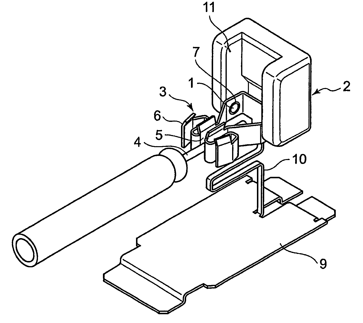
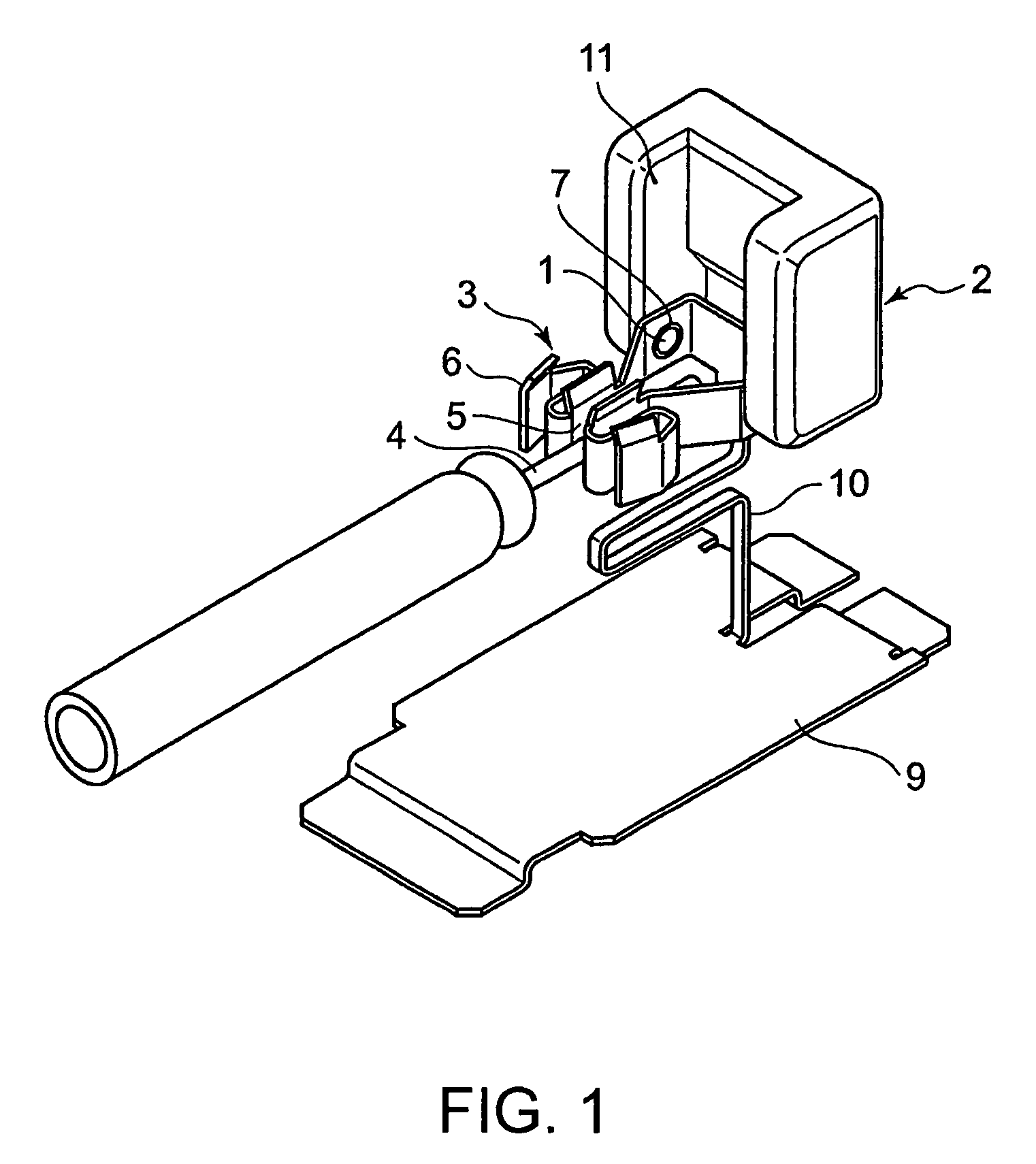
[0051]Referring to FIGS. 1, 2A, and 2B, a description will be given of a lamp tube connector as a connecting member according to this invention. The lamp tube connector is used for connecting, as a connection object, a fluorescent lamp tube such as a cold cathode-ray tube having lead wires.

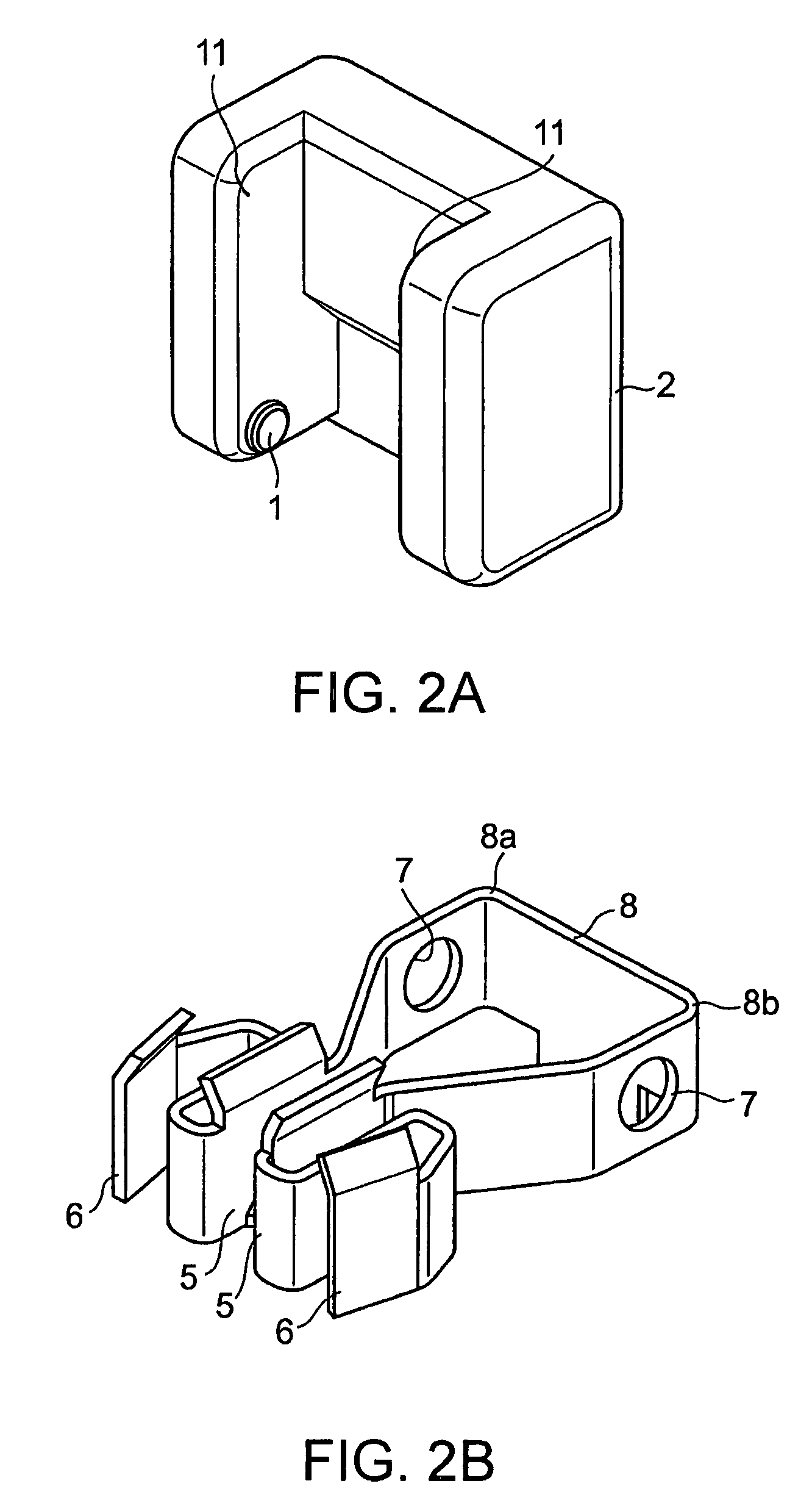
[0052]The lamp tube connector comprises an insulating slider 2 having a pair of projections, i.e. rotation shafts (only one of which is shown) 1, and a conductive contact 3 combined with the slider 2. The contact 3 comprises a pair of contact pieces or contact portions 5 for connection to a lead wire 4 of a lamp tube as a connection object, a pair of pressing portions 6 connected to the contact portions 5, respectively, a rotation shaft receiving portion 8 having a pair of shaft holes 7 rotatably receiving the rotation shafts 1, respectively, and a board connecting portion 9 as a terminal portion for connection to a board.

[0053]The rotation shaft receiving portion 8 has a multi-sided structure wit...

second embodiment

[0061]Referring to FIG. 7, a description will be given of a lamp tube connector according to this invention. In this lamp tube connector, the same reference symbols are assigned to the same or corresponding portions.

[0062]The lamp tube connector shown in FIG. 7 also comprises a slider 2 and a contact 3 combined with the slider 2. The slider 2 has slide shafts 1a. The contact 3 comprises contact portions 5 for connection to a lead wire of a lamp tube, pressing portions 6 adapted to be displaced by the slider 2, and a board connecting portion 9 (see FIGS. 16 and 17). A shaft receiving portion 81 comprises a bottom plate 17 provided between the contact portions 5 and a link portion 10 and a pair of guide plates 16 formed integrally with the bottom plate 17 and is formed with slide holes 7a each elongated in the front-rear direction and receiving the slide shafts 1a, respectively. With the slide shafts 1a being inserted into the slide holes 7a, the slider 2 is slidably held by the shaft...

third embodiment

[0066]Referring to FIGS. 9A and 9B, a description will be given of a lamp tube connector according to this invention. Also in this lamp tube connector, the same reference symbols are assigned to the same or corresponding portions.

[0067]In this lamp tube connector, a slider 2 and a contact 3 are incorporated in a housing 12. The housing 12 is press-fitted or locked onto a board connecting portion 9 of the contact 3 so as to be held. Contact portions 5 of the contact 3 and the slider 2 have floatability with respect to the board connecting portion 9 of the contact 3 and the housing 12.

[0068]Referring to FIG. 10, a floating mechanism will be described.

[0069]A flexible link portion 10 is connected between the contact portions 5 of the contact 3 and rotation shafts 1 or slide shafts 1a of the slider 2, and the board connecting portion 9. Through the link portion 10, the contact portions 5 of the contact 3 and the slider 2 have floatability with respect to the board connecting portion 9 o...


PUM


Abstract

A connecting member has a slider with rotation shafts and a contact combined with the slider. The contact has contact portions for connection to a connection object and pressing portions connected to the contact portions, respectively. By rotating the slider about the rotation shafts to press the pressing portions, the contact portions are displaced to be connected to the connection object. It may be configured to press the pressing portions by moving the slider in a straight or curved line. Further, it may be configured that the slider presses the pressing portions to thereby displace the contact portions in directions away from the connection object.

Description

[0001]This application claims priority to prior applications JP 2006-188700 and JP2006-211326, the disclosures of which are incorporated herein by reference.BACKGROUND OF THE INVENTION[0002]This invention relates to a connecting member and a connector, such as a direct-type lamp socket capable of connecting a lamp tube as a connection object.[0003]Thin lamp tubes such as CCFLs or EEFLs have been used as light sources in backlight modules of large liquid crystal displays. The type that directly irradiates light of lamp tubes onto a liquid crystal panel from its back side is called a “direct type”, which is excellent in light utilization efficiency and thus is optimal for a backlight of a liquid crystal display such as a monitor or a television that requires high brightness.[0004]The conventional direct-type backlight modules have several types.[0005]In one type, a plurality of lamp tubes are disposed at intervals on a metal housing, called a chassis, of a backlight module. Each lamp ...

Claims


Application Information

Patent Timeline
Patent Type & Authority Patents(United States)
IPC IPC(8): H01R33/08
CPCH01R13/193H01R33/02G02F1/133604H01R33/18
Inventor KATO, NOBUKAZUKUROIWA, MASAKAZUKATO, RINTAROKAMATA, KAZUSHI
Owner JAPAN AVIATION ELECTRONICS IND LTD
Why Eureka
Try Eureka