Syringe barrel and cylinder holder

a cylinder and syringe technology, applied in the field of syringe and cylinder holder, can solve the problems of difficult manual handling, difficult to make intense jobs, and the opening length of the flange insert groove cannot be large, and achieve the effect of easy mounting and high viscosity

Inactive Publication Date: 2009-03-17
NEMOTO KYORINDO KK
View PDF3 Cites 8 Cited by
  • Summary
  • Abstract
  • Description
  • Claims
  • Application Information

AI Technical Summary

Benefits of technology

[0008]The present invention has been achieved in view of the above described problems, and its object is to provide a syringe barrel a cylinder holder, where the syringe is not easily broken in injecting liquid of high viscosity at high pressure and can be easily mounted.

Problems solved by technology

Injection of a chemical solution having high viscosity such as a contrast agent for X ray CT imaging and a contrast agent for MRI (magnetic resonance imaging apparatus) requires high pressure, causes difficulty in manual handling, and makes intense jobs.
However, to prevent the slip-off, it is necessary to secure a certain level of the arc length of the flange insert groove and therefore the opening length of the flange insert groove cannot be made large.
The reason for this design is also that if the clearance is designed to zero completely, mounting may be sometimes impossible due to certain extent production error to be taken into consideration because the syringe barrel and the cylinder holder (including the adaptor) are usually formed of different materials.
Consequently, slight backlash and play in mounted condition is inevitable.
However, if there is an error in the mounting procedure, the syringe may sometimes be raised from the right position.

Method used


Image

  • Syringe barrel and cylinder holder
  • Syringe barrel and cylinder holder
  • Syringe barrel and cylinder holder

Examples


Embodiment Construction

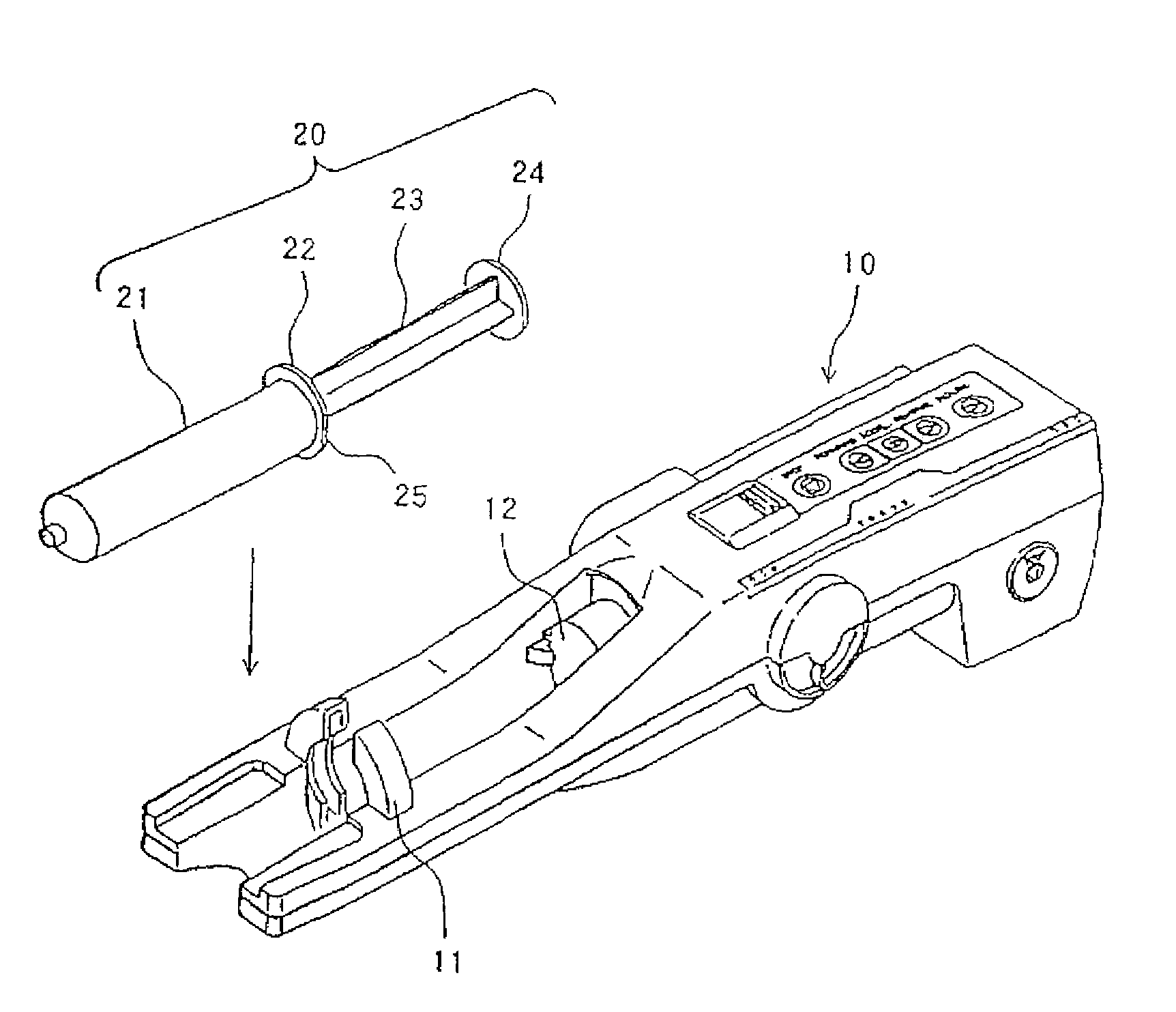
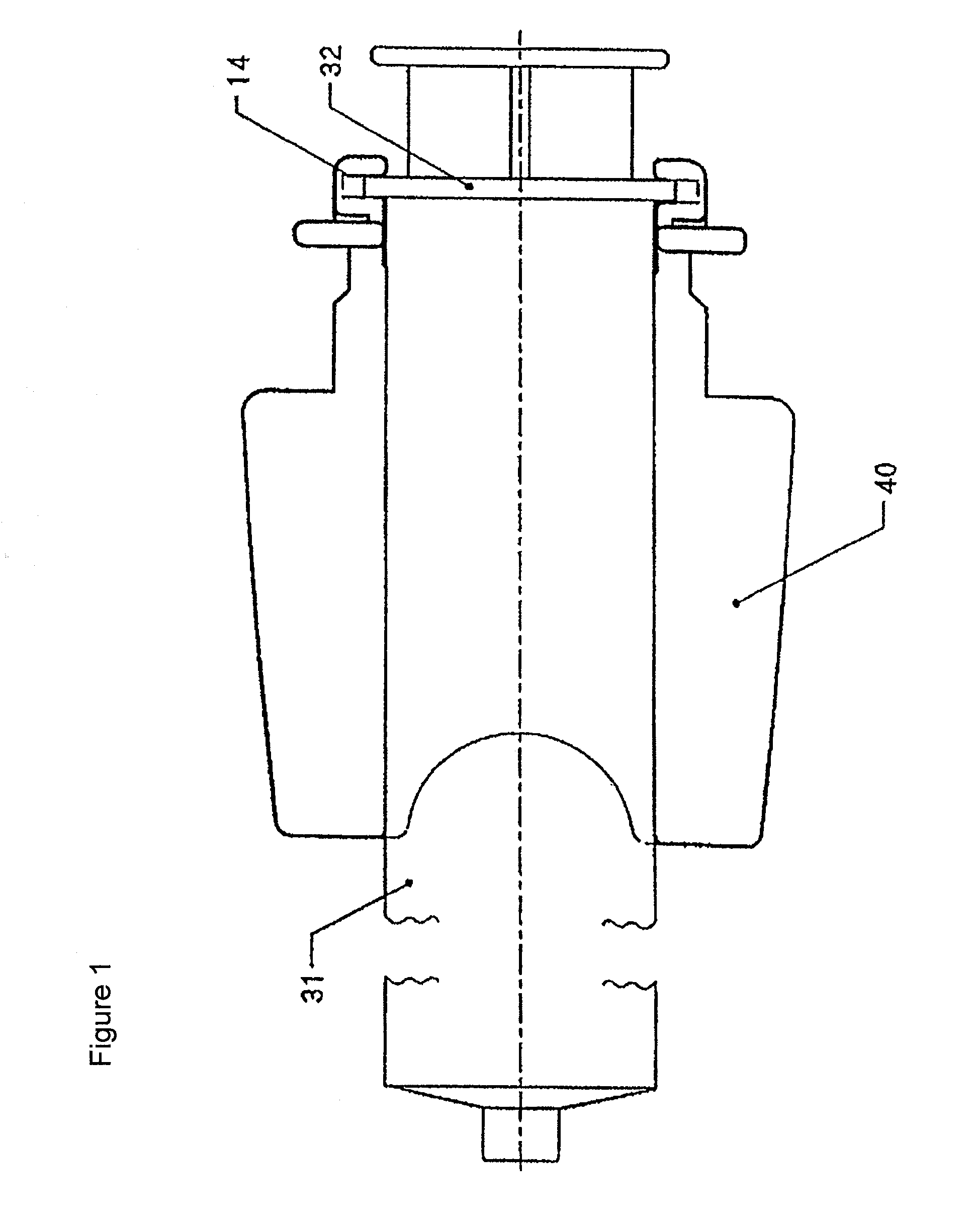
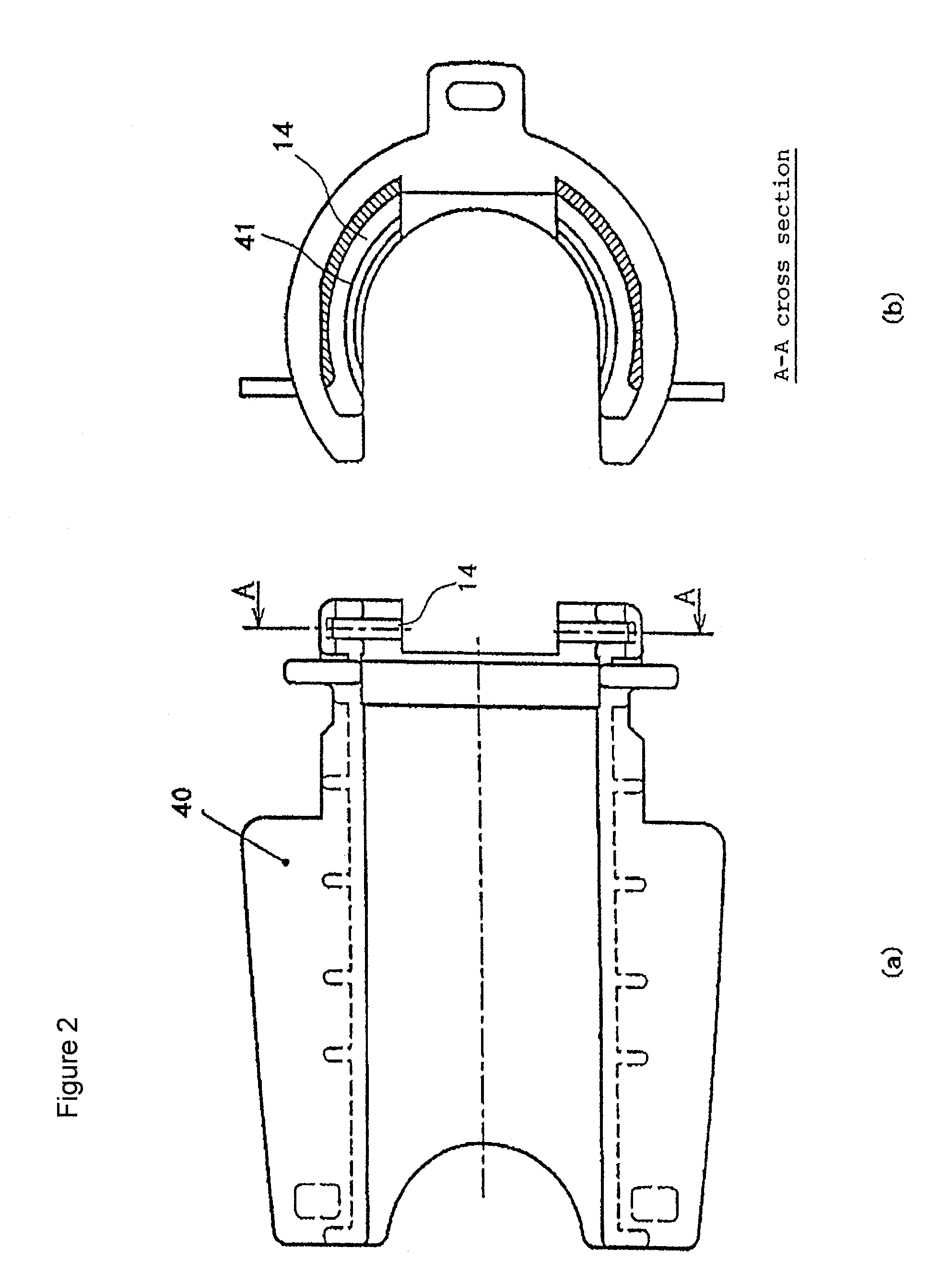
[0068]FIG. 1 shows the state in which a flange 32 of a syringe barrel 31 is fitted in a flange insert groove 14 of an adaptor 40 (cylinder holder). FIG. 2 shows the adaptor 40 in which FIG. 2(a) is a plan view seen from an attaching direction of the syringe barrel and FIG. 2(b) is an A-A cross section in FIG. 2(a) viewed from rear side. FIG. 3 is an enlarged cross sectional view of a portion of the flange insert groove 14. A guide groove 41 is formed in an arcuate shape on a front sidewall surface of the flange insert groove 14 provided in the adaptor.

[0069]In the meantime, FIG. 4 shows the flange of the syringe barrel, which is used together with the adaptor, viewed from the tip side of the syringe ((a) is a whole view of the front surface and (b) is an enlarged view of the part B of (a)). As shown in this drawing, the front surface of the flange 32 is provided with arcuate guide projections 33 (33a, 33b). An F-F cross section of FIG. 4 is shown in FIG. 5(a), and a C-C cross sectio...


PUM


Abstract

An arcuate guide projection is provided on a front surface of a flange of a syringe barrel and an arcuate guide groove for guiding the guide projection is provided on a front sidewall surface of a flange insert groove of a cylinder holder. When the syringe is mounted, the guide projection and the guide groove are brought into engagement thereby preventing the flange from slipping off upwardly.

Description

[0001]This application is a continuation of U.S. patent application Ser. No. 10 / 781,124 filed on Feb. 18, 2004, which application is a divisional of U.S. patent application Ser. No. 10 / 211,099 filed on Jul. 31, 2002 and also claims foreign priority to Japanese Patent Application No. 2001-233604, filed Aug. 1, 2001.FIELD OF THE INVENTION [0002]The present invention relates to a syringe and a cylinder holder which are suitable for injection at high injection pressure using a driving mechanism such as an automatic injection device.DESCRIPTION OF THE RELATED ART [0003]Syringes are used for injection of liquid in various fields typically including a medical field. Injection of a chemical solution having high viscosity such as a contrast agent for X ray CT imaging and a contrast agent for MRI (magnetic resonance imaging apparatus) requires high pressure, causes difficulty in manual handling, and makes intense jobs. Therefore, it is general to effect injection using a mechanical syringe dr...

Claims


Application Information

Patent Timeline
Patent Type & Authority Patents(United States)
IPC IPC(8): A61M1/00A61M5/00A61M5/145A61M5/31A61M5/20
CPCA61M5/14546A61M5/007A61M5/1456A61M5/1458A61M5/145
Inventor NEMOTO, SHIGERU
Owner NEMOTO KYORINDO KK
Why Eureka
Try Eureka